cutmaster a60
SERVICE 5-6 Manual 0-4981
5.06 Circuit Fault Isolation
WARNING
The following procedures should not be attempted
by anyone who has not had proper training or
authorized to do so.
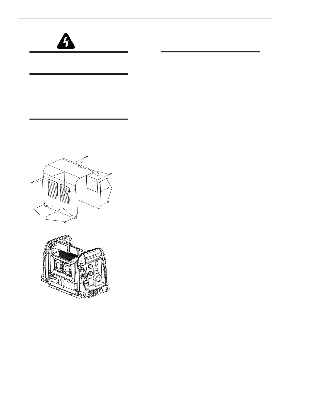
A. Cover Removal
1. Remove the upper and lower screws which
secure the cover to the main assembly. Do not
loosen the lower screws inside the cut out slots
in the bottom of the cover.
Note
The upper screws and lower screws are not the
same. Do not mix them. The upper screws are
for threading into the plastic of the front and rear
panels. DO NOT use the finer threaded lower
screws for this.
Upper
Screws
Lower
Screws
Lower
Screws
Art # A-08317
Slots
2. Carefully pull the Cover up and away from the
unit.
B. Cover Installation
1. Reverse previous procedures for cover installa-
tion.
NOTE
When installing the upper screws, attempt to
reuse the original threads. The easaiest way to
do this is by turning the screw counter-clockwise
until you feel the threads lign up, then begin to
turn the screw clockwise to tighten to 15-18 in.
lbs.. Do not over tighten.
C. Filter Element Assembly Replacement
The Filter Element Assembly is in the rear panel. For
better system performance, the filter element should be
checked per the Maintenance Schedule (Subsection 5.02),
and either cleaned or replaced.
1. Remove power from the power supply; turn off
the gas supply and bleed down the system.
2. Remove the system cover. See "A Cover Re-
moval" in this section.
3. Locate the internal air line and the fitting from
the filter assembly. Number 1 in the following
illustration.
4. Hold a wrench or similar tool against the lock-
ing ring on the filter assembly fitting, then pull
on the hose to release it. (Numbers 2 and 3 in the
following illustration).