EasyManuals Logo

Thermal Dynamics A60 CUTMASTER User Manual

Thermal Dynamics A60 CUTMASTER
116 pages
To Next Page IconTo Next Page
To Previous Page IconTo Previous Page
Page #79 background imageLoading...
Page #79 background image
cutmaster a60
Manual 0-4981 4T-45 OPERATION
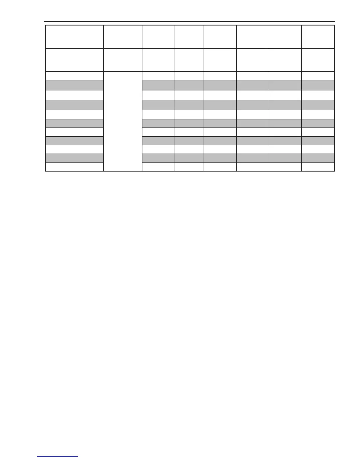
Material
Thickness
Gas Pressure
(Air)
Arc Voltage
Torch
Working
Height
Travel Speed
Initial
Piercing
Height
Pierce Delay
Kerf Width
@ Rec.
Speed
(mm)
Bar
(torch lead
length)
Volts (mm) (mm/min) (mm) (sec) (mm)
1
5.9 (7.6m)
6.2 (15.2m)
113 3.3 9020 5.1
0.00
2.4
2 116 3.3 7595 5.1
0.00
2.2
3 120 3.3 6165 5.1
0.10
2.0
4 121 3.3 5045 5.1
0.20
2.1
5 122 3.3 3955 5.1
0.20
2.2
6 124 3.3 2905 5.1 0.30 2.3
8 132 4.8 2010 5.1 0.40 2.3
10 140 4.8 1430 5.1 0.50 2.3
12 142 4.8 1045 5.1 0.60 2.6
15 146 4.8 730 5.1 0.75 2.7
20 157 4.8 330 Edge Start 3.2
BOLD TYPE indicates maximum piercing parameters. BOLD ITALIC indicates edge starts only.

Table of Contents

Other manuals for Thermal Dynamics A60 CUTMASTER

Questions and Answers:

Question and Answer IconNeed help?

Do you have a question about the Thermal Dynamics A60 CUTMASTER and is the answer not in the manual?

Thermal Dynamics A60 CUTMASTER Specifications

General IconGeneral
BrandThermal Dynamics
ModelA60 CUTMASTER
CategoryWelding System
LanguageEnglish

Related product manuals