SERVICE TROUBLESHOOTING 20 Manual 0-2582
A-01400
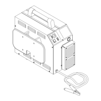
Pilot Output PC Board
E23
Wire #17
E24
Wire #16
Top
7. Faulty Logic PC Board
Measure for 15 VDC on Logic PC Board from J5-6
to J5-7.
a. If voltage is less than 10 VDC, replace Logic PC
Board
8. Faulty PCR Relay
Install a jumper between wires #12 and #14. Re-
try piloting again.
a. If torch pilots with jumper installed, replace PCR
Relay
4.08 Main Arc Problems
Locate your symptom below:
A. Main cutting arc will not initiate
1. Work cable not connected.
a. Connect work cable.
2. Faulty current sensor
Check the following indicators inside the Power
Supply:
• Pilot indicator (D33) on the Logic PC Board is ON
during pilot then OFF during main arc transfer
• CSR indicator (D31) on the Logic PC Board is OFF
during pilot then ON during main arc transfer
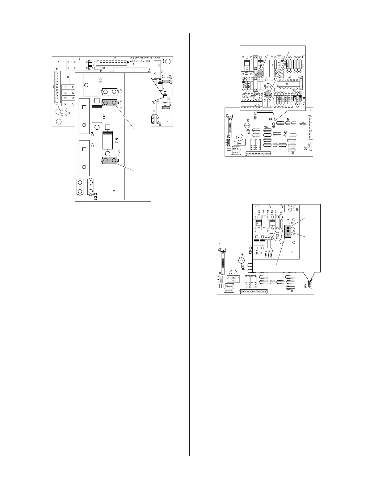
A-01405
Logic PC Board
D31
D33
While trying to transfer measure voltage at J17-1 to
J17-2 on the Logic PC Board.
Logic PC Board
A-01406
J17
Pin 1
Pin 2
If voltage is approximately 12 vdc replace the current
sensor.
If voltage is less than 2 vdc replace the Logic PC Board.
B. When operating at amperages over 35 amps the
amperage drops off after main cutting arc initiates
Check the following indicator inside the Power Sup-
ply:
• Drag indicator (D35) on the Logic PC Board is
ON when the torch tip comes in contact with
the workpiece.
1. Cutting tip in contact with the workpiece.
a. Maintain standoff distance 1/8"-3/8" between
cutting tip and workpiece.
 Loading...


