Manual 0-2582 31 REPLACEMENT PROCEDURES
5.05 Access Panel Parts
Replacement
NOTE
Refer to Section 6.04 for parts list and overall de-
tail drawing.
A. CURRENT Knob Replacement
1. Turn the CURRENT adjustment fully counter clock-
wise and note the location of the pointer on the
knob.
2. Loosen the screw securing the Current Knob to the
potentiometer shaft.
3. Remove the old knob.
4. Place the replacement Current Knob on to the po-
tentiometer shaft with the location of the pointer
the same as noted in step 1.
5. Tighten the screw to secure the knob to the poten-
tiometer shaft.
B. ON/OFF Switch Replacement
1. Unlatch the Access Panel to gain access to the rear
of the ON/OFF Switch.
2. Disconnect all the wiring to the ON/OFF Switch.
3. Squeeze the top and bottom of the switch while
pulling it out of the Access Panel
4. Install the replacement ON/OFF Switch by revers-
ing the above procedure.
C. RUN/SET Switch Replacement
1. Unlatch the Access Panel to gain access to the rear
of the RUN/SET Switch.
2. Disconnect all the wiring to the RUN/SET Switch.
3. Squeeze the top and bottom of the switch while
pulling it out of the Access Panel
4. Install the replacement RUN/SET Switch by re-
versing the above procedure.
D. Pot/LED PC Board Assembly Replacement
1. Turn the CURRENT adjustment fully counter clock-
wise and note the location of the pointer on the
knob.
2. Loosen the screw securing the Current Knob to the
potentiometer shaft.
3. Remove the Current Knob.
4. Unlatch the Access Panel to gain access to the Pot/
LED PC Board.
5. Remove the Pot/LED PC Board from the four stand-
offs.
6. Disconnect the connector at J14 of the Pot/LED PC
Board.
7. Install the replacement Pot/LED PC Board by re-
versing the above procedure.
E. Access Panel Replacement
1. Remove the Right Side Panel per Section 5.04-C.
2. Remove the following components from the Ac-
cess Panel:
• Current Knob per paragraph 'A' above.
• ON/OFF Switch per paragraph 'B' above.
• RUN/SET Switch per paragraph 'C' above.
• Pot/LED PC Board per paragraph 'D' above.
3. Remove the two nuts and washers securing the
Access Panel to the Right Side Panel.
4. Install the replacement Access Panel by reversing
the above procedure.
5.06 Front Panel Parts Replacement
NOTE
Refer to Section 6.05 for parts list and overall de-
tail drawing.
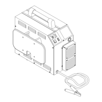
A. Work Cable Replacement
1. Remove the Left Side Panel per Section 5.04-B.
2. Remove the Work Cable connection from the lower
FET/Heatsink Assembly at E18 (OUTPUT) termi-
nal.
3. Remove the Work Cable strain relief from the Front
Panel .
4. Pull the Work Cable from the unit.
5. Install the replacement Work Cable by reversing
the above procedure.
B. Current Sensor Replacement
1. Remove the Work Cable per paragraph 'A' above.
2. Disconnect the ribbon cable from the Current Sen-
sor at J17 of the Logic PC Board.
3. Remove the four screws securing the sensor to the
standoffs at the rear of the Front Panel, behind the
Work Cable Strain Relief.
4. Install the replacement Current Sensor by revers-
ing the above procedure.
 Loading...


