Manual 0-2582 21 SERVICE TROUBLESHOOTING
2. Faulty Logic PC Board
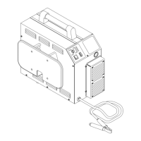
If torch tip is off the workpiece and the drag indi-
cator, D35, on the Logic PC Board is still ON, then
replace the Logic PC Board
A-01407
Logic PC Board
D35
4.09 Test Procedures
The test procedures in this subsection are referenced in
the troubleshooting section.
A. Safety Precautions
1. Significant DC Voltage exists after removal of input
power. Allow 2 minutes for discharge time. Voltage
measured on input capacitors must be zero before
performing service on the power supply.
2. Do Not touch electrical components with any part of
the human body when power is applied.
3. Keep away from any moving parts.
4. Hot surfaces can cause severe burns. Allow equip-
ment to cool before servicing.
5. Electrostatic discharge can damage printed circuit
board assemblies. Transport printed circuit boards in
proper anti-static shielded packages. Use proper
grounding techniques with wrist strap before handling
printed circuit boards.
6. Misaligned plugs can cause printed circuit board dam-
age. Be sure plugs are properly aligned and com-
pletely seated.
7. Excessive pressure can damage printed circuit board.
Use only minimal pressure and gentle movement
when disconnecting or connecting printed circuit
board plugs.
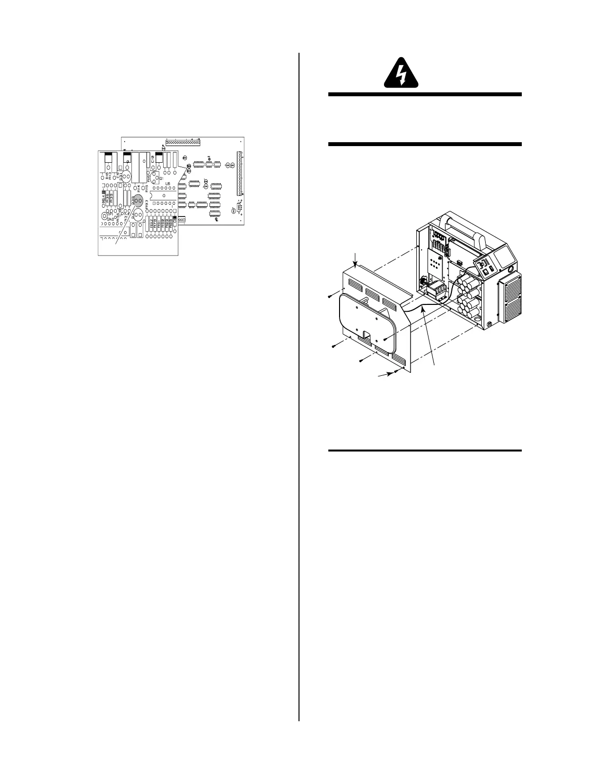
B. Opening Power Supply Enclosure
The left side panel of the Power Supply must be removed
to gain access to the input power connections and the
input voltage selection.
WARNING
Disconnect primary power at the source before as-
sembling or disassembling the Power Supply, torch
parts, or torch and leads assemblies.
1. Using a phillips head screw driver remove the five
screws which secure the left side panel (viewed from
front of unit) to the frame assembly.
Screws
(5 Places)
Left Side
Panel
A-01346
Ground Wire
2. Carefully pull the left side panel from the Power Sup-
ply a short distance (see note).
NOTE
There is a ground wire attached to the side panel.
3. Remove the nut securing the ground wire to the side
panel.
4. Close the enclosure by reversing the above steps.
C. Diode Testing Basics
Testing of diode modules requires a digital volt/ohmme-
ter that has a diode test scale. Remember that even if the
diode module checks good, it may still be bad. If in doubt,
replace the diode module.
1. Locate the diode module to be tested.
2. Remove cables from mounting studs on diodes to iso-
late the module.
3. Set digital volt/ohmmeter to diode test scale.
4. Using the Figures for each test, check each diode in the
module. Each diode must be checked in forward bias
(plus to negative) and reverse bias (negative to plus)
direction.
 Loading...


