SERVICE TROUBLESHOOTING 22 Manual 0-2582
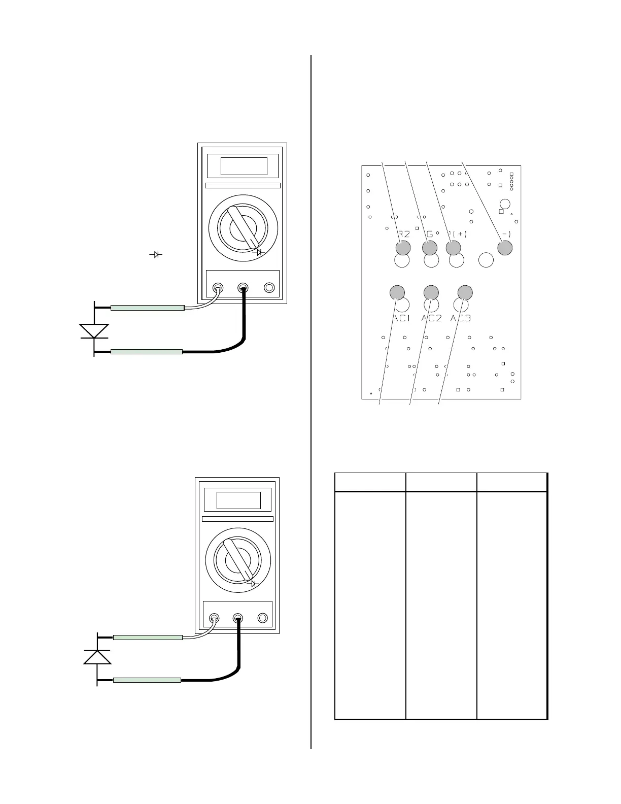
5. Connect the volt/ohmmeter positive lead to the an-
ode (+) of the diode and the negative lead to the cath-
ode (-) of the diode for forward bias testing (refer to
following figure). A properly functioning diode will
conduct in the forward bias direction and indicate be-
tween 0.3 to 0.9 volts.
0.75
VR
COM
A
A-00307
Anode
Cathode
Forward Bias
Diode Conducting
+
_
Diode Test Symbol
Testing Diode Forward Bias
6. Reverse the meter leads across the diode for reverse
bias testing (refer to following figure). A properly
functioning diode will block in the reverse bias direc-
tion and depending on the meter function will indi-
cate an open or “OL”.
OL
VR
COM
A
A-00306
Anode
Cathode
Reverse Bias
Diode Not Conducting
+
_
Testing Diode Reverse Bias
7. If a diode checks bad, replace the diode module.
8. Reconnect all cables to proper terminals.
D. Input PC Board Test
Locate the Input PC Board behind the EMC Filter As-
sembly and check for shorted input diode.
R2
G
(+) (-)
AC1
AC2
AC3
A-01408
Input PC Board
Remove AC power and with an ohmmeter set on the di-
ode range make the following checks:
Meter (+) Meter (-) Indication
AC1 R2 Diode Drop
R2 AC1 Open
AC2 R2 Diode Drop
R2 AC2 Open
AC3 R2 Diode Drop
R2 AC3 Open
AC1 (-) Open
(-) AC1 Diode Drop
AC2 (-) Open
(-) AC2 Diode Drop
AC3 (-) Open
(-) AC3 Diode Drop
The meter should indicate a diode drop in one direction
and an open in the other direction for each check.
 Loading...


