Manual 0-2582 33 REPLACEMENT PROCEDURES
3. Remove the clear Input PC Board Insulator sheet.
4. Remove the two screws at 'R2' and 'G'.
5. Carefully pull the Input PC Board from the unit far
enough to disconnect the wiring connections to the
component side of the PC board.
6. Install the replacement Input PC Board by revers-
ing the above procedure noting the following:
NOTE
Failure to properly tighten the seven screws secur-
ing the Input PC Board to the Diode Bridge will
cause damage to the unit.
• The five screws securing the wiring and Input
PC Board to the Diode Bridge must be tight
enough to prevent the wires from moving.
• The two screws securing the Input PC Board to
the Diode Bridge at 'R2' and 'G' must be tight.
D. Input Diode Bridge Assembly Replacement
1. Remove the Left Side Panel per Section 5.04-B.
2. Remove the Right Side Panel per Section 5.04-C.
3. Remove the Input PC Board per paragraph 'C'
above.
4. Remove the two nuts securing the Input Diode
Bridge to the Center Chassis.
5. Remove the Input Diode Bridge Assembly from
the unit.
6. Remove the Thermal Pad from the Center Chassis.
7. Remove the Input Heatsink on the right side of the
unit.
8. Remove the Thermal Pad from the Input Heatsink.
9. Install the replacement Input Diode Bridge Assem-
bly and new Thermal Pad by reversing the above
procedure (see Note).
NOTE
The two nuts removed in Step 3 must be torqued
to 35 in-lbs when reinstalled.
E. Logic PC Board Replacement
1. Remove the Left Side Panel per Section 5.04-B.
2. Carefully remove all cable connections from the
Logic PC Board noting the location of each.
3. Remove the four screws securing the Logic PC
Board to the standoffs.
4. Install the replacement Logic PC Board by revers-
ing the above procedure.
F. Gate Driver PC Board Replacement
1. Remove the Left Side Panel per Section 5.04-B.
2. Remove the Logic PC Board per paragraph 'E'
above.
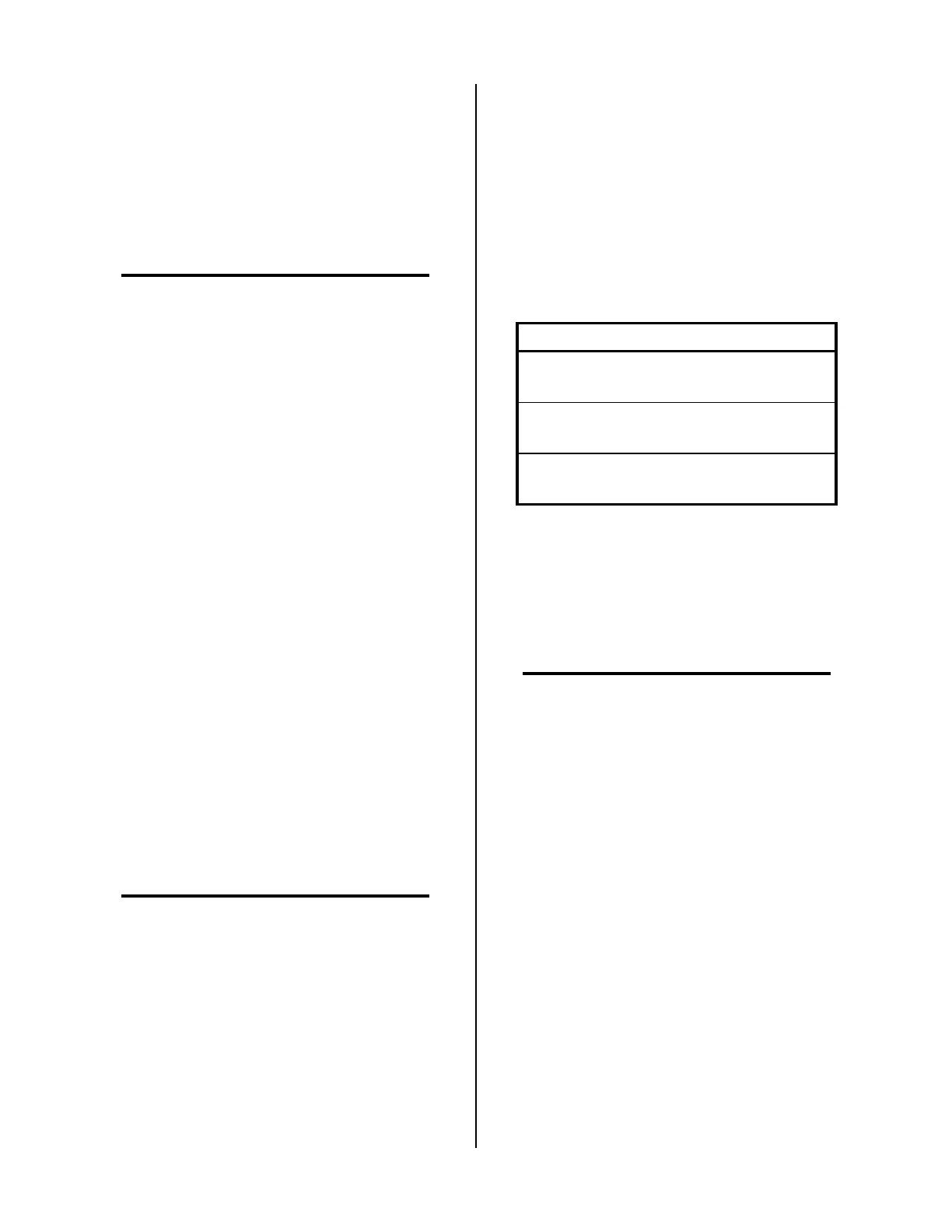
3. Carefully remove all cable connections to the Gate
Driver PCB Assembly noting the location of each
per the following chart:
Connection Description of Cable
J9
Ribbon Cable from Logic
PC Board
J8
Ribbon Cable from Top
FET/Heatsink Assembly
J7
Ribbon Cable from Bottom
FET/Heatsink Assembly
4. Remove the four screws securing the Gate Driver
PC Board to the four standoffs.
5. Reinstall the replacement Gate Driver PCB Assem-
bly by reversing the above procedure.
G. FET/Heatsink Assembly Replacement
NOTE
The two FET/Heatsink Assemblies are identical and
are removed in the same manner.
1. Remove the Left Side Panel per Section 5.04-B.
2. Place the unit on it's right side.
3. Remove the Ribbon Cable plug at J6 on the FET/
Heatsink Assembly. To remove the cable, push
down on the locking tab and pull the cable plug
out of the connector.
4. Disconnect all the wire lug connections to the FET/
Heatsink Assembly.
 Loading...


