ELECTRICAL & REFRIGERATION INFORMATION 27
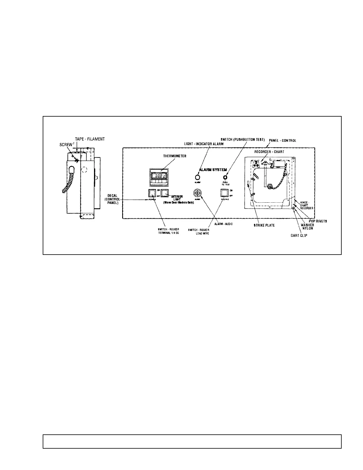
CONTROL ANNUNCIATOR PANEL
ALARM SYSTEM
This alarm is designed to queue the attendant of an
immediate alarm condition. The system has both an
audio and visual alarm signal for alarming on high cav-
ity temperature, plus a contact to connect a remote
alarm. The alarm system has a battery supply and will
operate whether or not the cabinet has power.
1. Upon installation and after the cabinet is down to
temperature, remove the paper tab separating the
batteries in their holder. The battery holder is locat-
ed on the reverse side of the control annunciator
panel. Batteries are non-rechargeable. The batter-
ies can be reached from the top of the cabinet with
the aid of a step ladder, or by removing the control
panel and resting it on top of the cabinet.To do this,
remove the two screws from the top mounting tabs
and lift the panel off of the mounting studs.
2. The high temperature alarm indicates to the atten-
dant that the cavity conditions are in excess of the
predetermined high temperature limit. The tempera-
ture alarm is signalled from the optional chart
recorder installed, or the alarm thermostat located
behind the control annunciator panel. To set the
alarm thermostat, simply position the pointer on the
desired temperature alarm limit. See the section
“Optional Chart Recorder” for setting the alarm limit
when a chart recorder is installed.
3. A button is provided for testing proper alarm system
signaling. When depressed, the batteries are used
to power the visual alarm indicator, audio alarm indi-
cator, and 6V DC remote alarm contacts. This test
should be conducted daily to insure functionability
and satisfactory battery charge. Batteries should be
replaced at least once a year with 4 good quality
alkaline “D” cell batteries as this is the only power
for the alarm system.
4. The system is provided with a rocker switch that
may be used to silence the audio portion of the
alarm signal during an alarm condition. No other
functions are affected by this switch. If the toggle
switch is turned off to silence the audio alarm, be
sure to turn the switch back on as soon as the cab-
inet temperature returns to normal and the signal
light goes out.
GENERAL
The control annunciator panel is designed to provide
the user with a convenient way of monitoring cavity
conditions, turning the interior light on and off and
turning the cabinet power on and off.
1. Cabinet power is controlled by an ON/OFF switch.
2. The interior cabinet light is controlled by a rocker
switch on the control panel on glass door units and
a push button switch on solid door units.
3. The digital process meter monitors cavity tempera-
ture and displays the measurement on a LCD
screen in degrees centigrade (°C). This thermome-
ter is both solar powered and battery assisted. In
the event there is not enough light the 3 volt battery
will take over. The battery is located on the rear of
the thermometer and is held in place by a metal clip.
The thermometer is not tied to any electrical circuit.