28 ELECTRICAL & REFRIGERATION INFORMATION
5. Contacts are provided on the reverse side of the
control annunciator panel to power a remote alarm
from the cabinet battery supply. The remote alarm
should be a low ampere 6 V DC device such as an
audio alarm or small signal light to avoid running
down the battery too fast.
EMERGENCY PROCEDURE PLANNING
Post adjacent to or on the cabinet instructions to follow
in the event of an alarm condition.
1. Persons to be notified and the telephone numbers
of each.
2. The location of other refrigerators/freezers that
might have space for emergency storage.
3. The telephone number to call for electrical/refriger-
ation repair.
CHART RECORDER
The circular chart recorder is designed for conve-
nience in maintaining essential records of cavity tem-
perature twenty-four hours a day. The drive motor is
supplied from the cabinet power supply and will oper-
ate any time the master power supply switch is “ON”
and the cabinet is plugged in.The recorder will contin-
ue to indicate temperature in a power failure condition
for approximately 24 hours with the 9-volt battery
backup installed.
CHART PAPER CHANGE
Press and hold the “change chart” button (#3) for one
second until the pen begins to move to the left of the
chart. To remove the chart, unscrew the knob at the
center of the chart. Position the new chart so that the
correct time line coincides with the time line groove on
the chart plate. Again push the “change chart” push-
button (#3) for one second until the pen begins to
move back onto the chart. Check to make sure that the
pen is marking on the paper. If not, lightly adjust the
pen arm to establish contact with the paper.
MARKING SYSTEMS:
MARK-A-MATIC II INKING SYSTEM
The pen consists of a self-contained ink reservoir with
a porous plastic stylus which is snapped around the
outer edge of the pen arm. Two (2) screws are provid-
ed at the top of the pen arm to adjust the length to
ensure that the pen tracks the time line on the chart.
Check the length after each pen replacement and
adjust accordingly if required. If the stylus does not
touch the chart, adjustment can be made by slightly
ben ding the pen arm in the center. Do not use more
pressure than is necessary to create a fine line.
Note: As the pen ink supply runs out the pen color will
become lighter.This indicates that the pen should be
replaced.
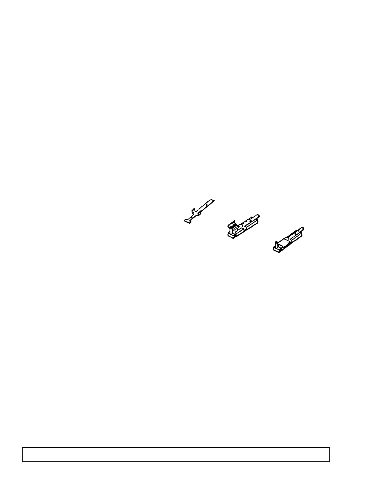
REPLACEMENT OF PEN
All recorders are provided with fiber tipped cartridge
pens. The body of the cartridge is color coded to des-
ignate the red (No. 1) and the blue (No. 2 optional)
pens. The pen is securely held on the special “U” clip
tab arm by means of a snap-on hinge at the bottom.
For ease of replacement it is suggested that the 2
screws that hold the pen arm be loosened and the pen
and arm be removed as an assembly. Unsnap the
plastic hinge, remove and discard the old pen.
Replace the new cartridge by opening the hinge and
snapping it securely around the pen arm.
Note: In non-inking units, replacement of the pen
is not necessary.