6 GENERAL INFORMATION
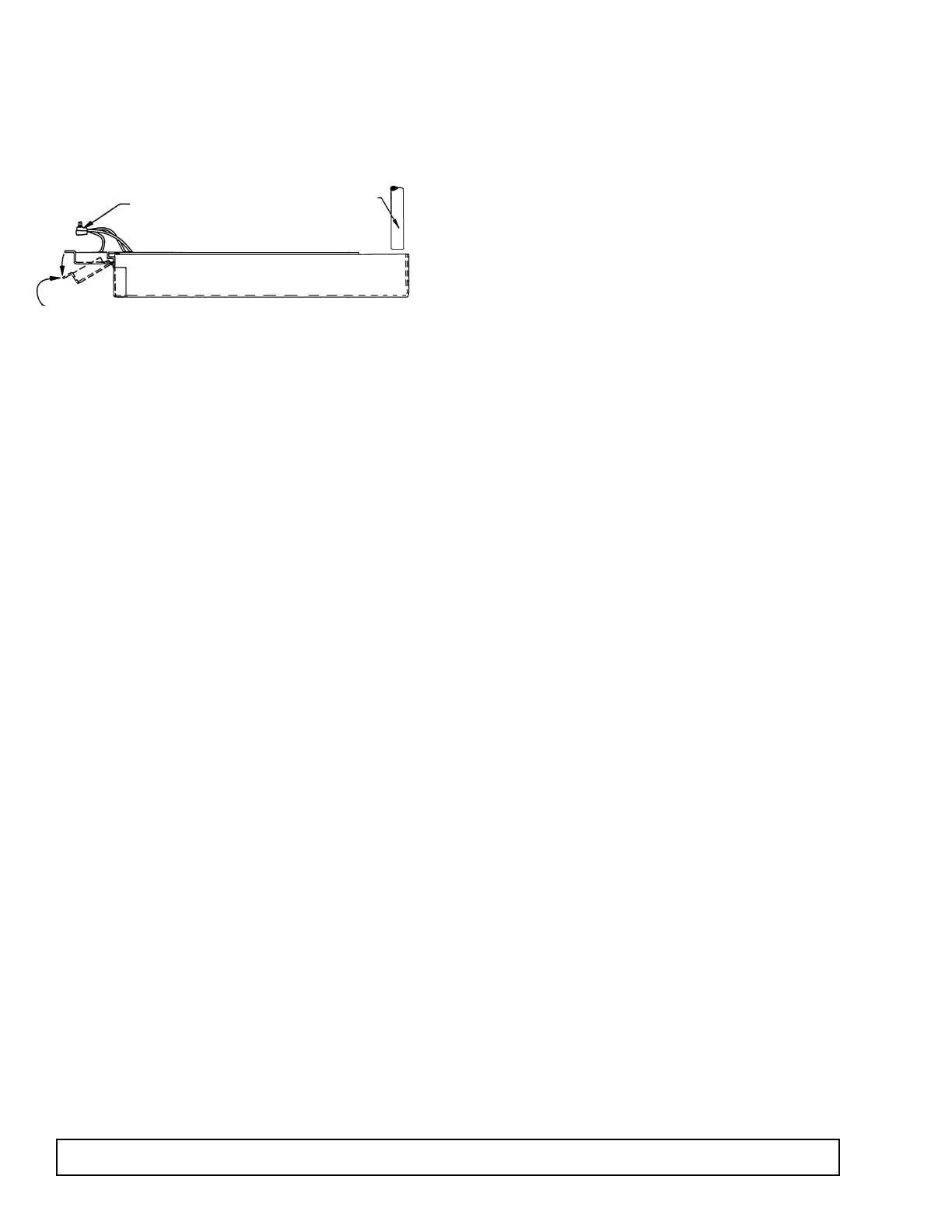
CONDENSATE PAN
INSTALLATION INSTRUCTIONS
MAKE SURE THE CABINET IS DISCONNECTED
FROM ITS POWER SOURCE
1. Remove and discard protective cover over electrical
receptacle on bottom of cabinet
2. Bend down front part of housing. (See above.)
3. Insert condensate evaporator pan assembly into the
slide supports on the underside of the cabinet by
pushing toward back of cabinet until it stops.
4. Plug supply cord into receptacle in underside of
cabinet.
5. Bend up front part of housing. Line up slot with
rivnut in cabinet bottom and insert thumbscrew
through slot onto rivnut in cabinet bottom. Insert
thumb screw through slot onto rivnut and tighten.
6. The assembly will now operate when power is sup-
plied to the cabinet.
7. Inspect rear of cabinet to ensure that the drain line
from the evaporator is properly positioned over the
condensate pan.
CABINET STARTUP
Once the cabinet has been located in its permanent
location and the proper power and grounding have
been provided, the following items must be checked or
completed:
1. Cut and remove the compressor hold-down band (if
applicable) so the compressor “floats” freely.
2. Check for traces of oil on the compressor pan which
could mean a broken or leaking refrigeration line.
UNDER NO CIRCUMSTANCE SHOULD THE
COMPRESSOR BE STARTED WHEN OIL IS PRE-
SENT UNTIL INSPECTED BY A SERVICE TECH-
NICIAN.
3. INSPECT THE FACTORY WIRING FOR
TERMINALS THAT MIGHT HAVE VIBRATED
LOOSE IN SHIPPING. TIGHTEN ALL SCREW-
TYPE TERMINALS.
4. Check the refrigeration lines to see that they are
“free” and no damage was done during shipping.
5. Check fan blade(s) for “free” operation.
6. Turn on the main power switch. Once the compressor
starts, the voltage should be checked at the compres-
sor terminals to determine if there is proper voltage to
the compressor. The voltage should not exceed 10%
above or below the rated compressor voltage.
EXAMPLE: If the voltage reads 115 volts with no load
and it drops below 103 volts when the compressor
starts, it may indicate that the supply wiring is too
small or that the wire run is too long.
7. Make sure that the drain line has not been dis-
lodged or broken during shipping and that the drain
trap terminates properly in the condensate pan or
floor drain. (See
Condensate Pan on top mounted
compressor.)
8. Listen for any unusual noise such as lines vibrating,
etc. Correct problem by tightening screws, slightly
bending tubing, etc.
9. Check proper tension on doors. (See Door Torque
Adjustment.)
10. Cabinet should not be loaded with product until
cabinet has operated for 24 hours and reached
desirable storage temperature.
EXPORT MODELS
Export model cabinets come equipped with an auto
transformer located in the unit compartment. The
selector switch can be set to various customer voltage
requirements - Factory Setting: Mid position for an
incoming voltage between 212V and 238V.
PRIOR TO STARTING THE CABINET
Supply voltage must be checked in order to determine
the correct position of the variable voltage switch
located on the auto transformer. This will ensure the
cabinet is operating at the correct optimum voltage. In
the event the transformer supply line plug does not
match the electrical outlet, the plug can be changed to
one with equal voltage-amperage rating.
Refer to page 41 for transformer layout.
DRAIN LINE FROM
EVAPORATOR - SEE
NOTE #7.
SUPPLY CORD