Insert the notched end of the memory module into the contact edge side of the memory slot. Press the
memory module in firmly, and pivot it downward until it snaps into place. Ensure that the memory module is
firmly installed in the slot and does not move easily.
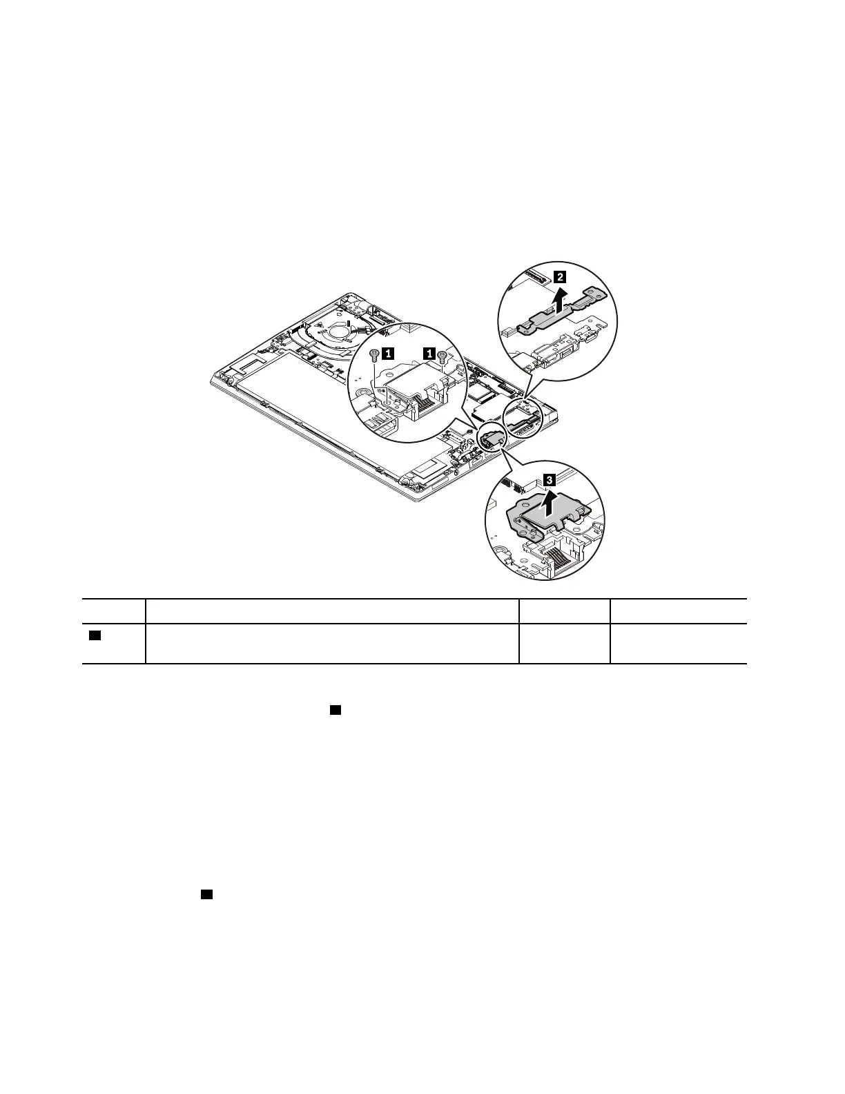
1070 Ethernet connector drop-down door
For access, remove this FRU:
• “1020 Base cover assembly” on page 67
Removal steps of the Ethernet connector drop-down door
Step Screw (quantity) Color
Torque
1
M2 × 4 mm, flat-head, nylon-coated (2)
Black 0.181 Nm
(1.85 kgf-cm)
When installing:
Ensure that the bracket removed in step
2 is mounted above the Ethernet connector drop-down door.
1080 Thermal fan assembly
For access, remove this FRU:
• “1020 Base cover assembly” on page 67
Removal steps of the thermal fan assembly
Note: Depending on the model, the thermal fan on your computer might look slightly different from the
illustration in this topic.
Loosen the screws
2 in ascending alphabetical order (a to d) as illustrated.
72
T480s Hardware Maintenance Manual