YOUR RECEIVER
P5
English
2.0 YOUR RECEIVER
2.1 Default PIN: 0000
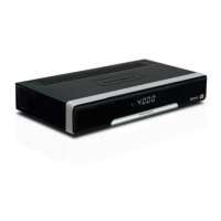
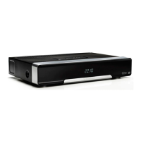
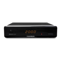
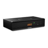
2.2 Front panel
Fig. 1
1. Power button: Switch the receiver to Standby or On.
2. P-/P+: To change channels without using the remote control
3. V-/V+ Decrease/Increase audio volume. V-/V+ and P+/P- double as navigation
buttons when in menu.
4. Remote control sensor:
Receives the signal from the remote control
5. Standby indicator:
Shows power state of the receiver
Green LED - receiver is turned on
Red LED - receiver is in standby mode
6. LED display: Shows channel number in operation and time in Standby
7. USB: For connection of USB pen drive for software upgrade storage devices
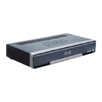
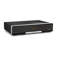
2.3 Rear panel
Fig. 2
1. Ethernet To connect to a network switch, router or modem
2. SAT IN To connect to the LNB of your satellite dish for reception of satellite
broadcast signal
3. SAT OUT To loop through the satellite signal to a second receiver
4. S/PDIF coaxial To connect to a digital or home cinema audio amplifier
5. USB For connection of USB pen drive for software upgrade storage devices or
HDD for Multimedia.
6. HDMI To connect to the HDMI input of your TV using a good quality HDMI cable.
7. TV SCART To connect to TV using a SCART cable
8. DC power To connect to the original included main power adapter (input 100 ~ 240 V
50~60 Hz/output 12 V DC
2.4 Remote Control
Fig. 3
1. q Turns the receiver ON/Standby
2. ! Turns the sound on or off
3. RED Flexible functions in OSD menu and Teletext
4. GREEN Flexible functions in OSD menu and Teletext.
5. YELLOW Flexible functions in OSD menu and Teletext.
6. BLUE In viewing mode: displays the schedule menu for easy setup timers; Flexible
functions in OSD menu and Teletext.
7. SUBTITLE Selects the subtitle language