TS 910 TRANSFER SWITCH
PM140 REV 0 12/02/09 32 Thomson Technology
18.6.1.2. Configuration Jumpers
The TSC 9 controller provides 9 user-configurable functions which utilize
jumpers located directly on the printed circuit board as per FIGURE 2.
They are used for configuration of main system operating parameters
such as voltage, phases and timers. Refer to Section 18.15
(CONFIGURATION INSTRUCTIONS) for further information.
18.6.1.3. KW Adjustment Switches
The TSC 9 controller provides 2 KW load adjustment switches which are
utilized when the KW Load Shed optional accessory is provided with the
transfer Switch. Additional information on TS 910 kW Load shed optional
accessory can be obtained from our Website
(www.thomsontechnology.com ).
18.6.1.4. Controller Isolation wiring Plug (J4)
A 20 pin wiring plug is utilized on the TSC 9 controller for connecting all
interconnecting wiring to the transfer switch mechanism. This plug can
be used for disconnecting all control power to the TSC 9 controller for
servicing or manual ATS operating procedure.
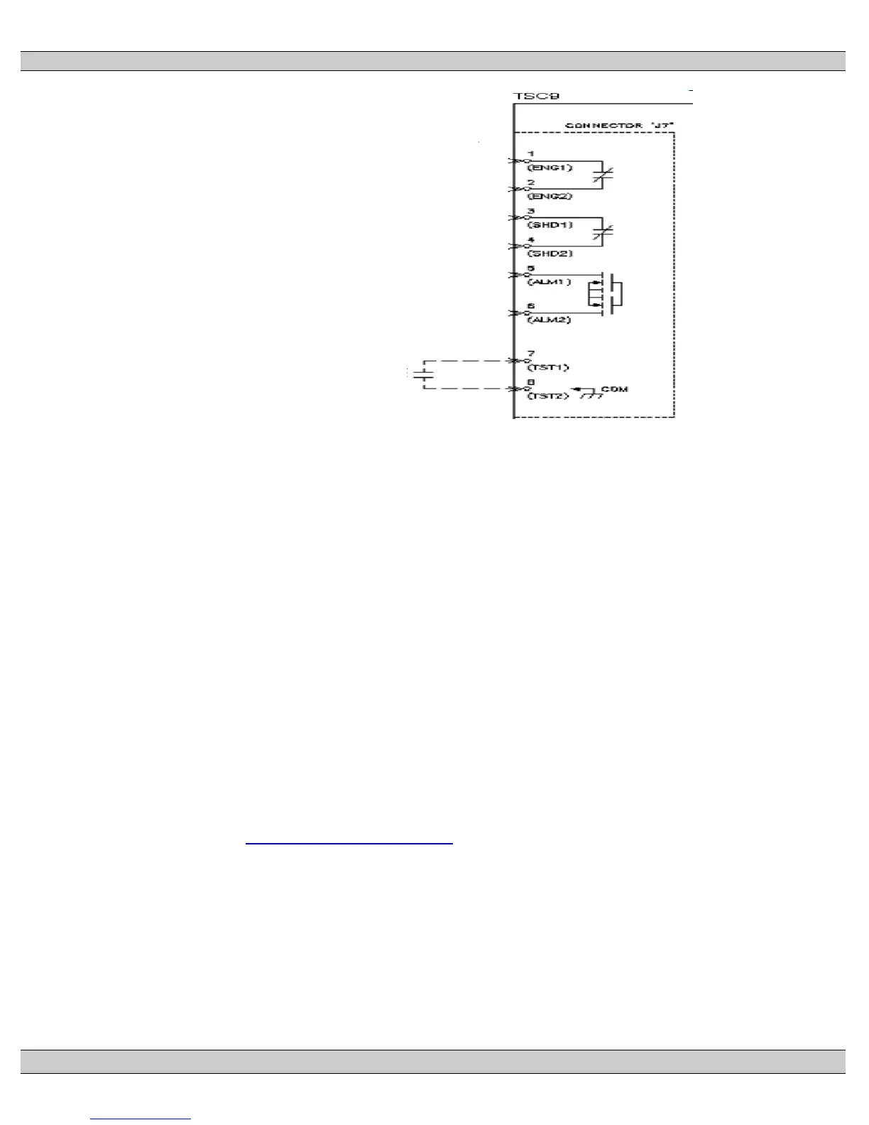
ENGINE START
(CONTACT CLOSES TO START ENGINE)
RATED 5A, 240VAC, 28VDC (RESISTIVE)
LOAD SHED
(CONTACT OPENS TO DISCONNECT
NON-ESSENTIAL LOADS)
RATED 5A, 240VAC, 28VDC (RESISTIVE)
ALARM OUTPUT
(CLOSE ON ALARM)
100Ma MAX LOAD, 120VAC, 24VDC
REMOTE TEST
CONTACT TO CLOSE TO INITIATE TEST
(OPEN TO TERMINATE TEST)
CONNECT ONLY A VOLTAGE FREE
CONTACT TO THIS INPUT