© 2013 Thorlabs GmbH478
DCx Cameras
Hint
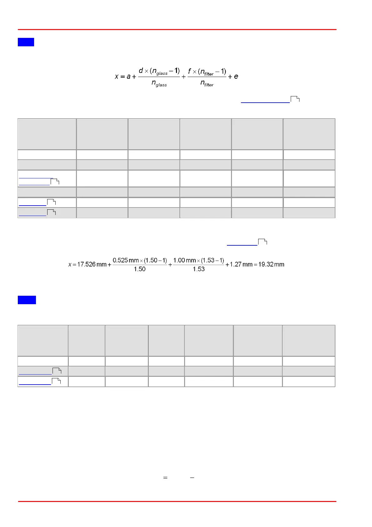
You can use the following formula to calculate the mechanical flange back distance:
The tolerances for the position accuracy of DCx camera sensors are given in the Position accuracy chapter.
Calculating the flange back distance for DCx Cameras with C-mount
Thickness sensor
glass [mm]
Active sensor
area to PCB
[mm]
Flange to active
sensor area
without filter glass
[mm]
Flange to active
sensor area with
filter glass [mm]
Sensor height
above the PCB
[mm]
Calculation example: UI-154x-xx with IR-cut filter
(a = 17.526 mm, d = 0.525 mm, nGlass = 1.50, f = 1mm, nFilter = 1.53; see Filter types table)
Calculating the flange back distance for DCC1545M and DCC1645C cameras with CS-mount
Note
For these cameras with CS-mount, the flange back distance is only 12.526 mm.
Thickness
sensor
glass [mm]
Active sensor
area to PCB
[mm]
Threaded
flange to
active
sensor area
Flange to active
sensor area
without filter
glass[mm]
Flange to active
sensor area with
filter glass [mm]
Sensor height
above the PCB
[mm]
5.4.5.2 Maximum Immersion Depth for Lenses
Some C-mount lenses reach deep into the camera flange. This may cause the lens to push against the back of the
filter glass inside the camera or even make it impossible to screw in the lens.
The table below indicates the maximum possible immersion depth for each DCx camera model. The actual
immersion depth of a lens is given in the relevant data sheet. As lens parts with a small diameter are allowed to
reach deeper into the camera flange, the immersion depths are specified based on the diameter.
Beside the immersion depth also the back focal length has to be considered, that means the distance between the
last lens and the sensor (named "bfl" in the image below). The back focal length can be calculated for C-mount with
the following formula:
x stands for the maximum immersion depth (see table below).
480
461
468
470
480
464
466
 Loading...