39
K10CR1 Cage Rotation Stage
Step Distance - The distance to move when a jog command is initiated. The step size
is specified in real world units (mm).
Backlash Correction - The system compensates for lead screw backlash during
reverse direction moves, by moving passed the demanded position by a specified
amount, and then reversing. This ensures that positions are always approached in a
forward direction. The Backlash Correction Distance is specified in real world units
(degrees). To remove backlash correction, this value should be set to zero.
Position Profiling
To prevent the motor from stalling, it must be ramped up gradually to its maximum
velocity. Certain limits to velocity and acceleration result from the torque and speed
limits of the motor, and the inertia and friction of the parts it drives.
The system incorporates a trajectory generator, which performs calculations to
determine the instantaneous position, velocity and acceleration of each axis at any
given moment. During a motion profile, these values will change continuously. Once
the move is complete, these parameters will then remain unchanged until the next
move begins.
The specific move profile created by the system depends on several factors, such as
the profile mode and profile parameters presently selected, and other conditions such
as whether a motion stop has been requested.
Bow Index – This field is used to set the profile mode to either Trapezoidal or S-curve.
A Bow Index of ‘0’ selects a trapezoidal profile. An index value of ‘1’ to ‘18’ selects an
S-curve profile. In either case, the velocity and acceleration of the profile are specified
using the Velocity Profile parameters on the Moves/Jogs tab.
The Trapezoidal profile is a standard, symmetrical acceleration/deceleration motion
curve, in which the start velocity is always zero. This profile is selected when the Bow
Index field is set to ‘0’.
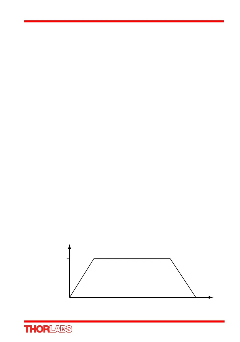
In a typical trapezoidal velocity profile, (see Fig. 6.4.), the stage is ramped at
acceleration ‘a’ to a maximum velocity ‘v’. As the destination is approached, the stage
is decelerated at ‘a’ so that the final position is approached slowly in a controlled manner.
Fig. 6.4 Graph of a trapezoidal velocity profile
velocity
maximum
velocity (v)
time
acceleration (slope) a

 Loading...


