64
DMC3S - Manual - 08 - 2021
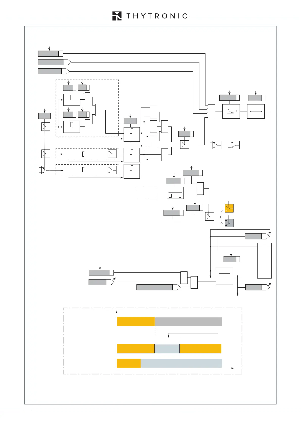
Fun_67S1.ai
I
L1
I
L1
∙cos
≥1
≥1
≥1
ON≡Inhibit (from IP>>, IPD>>> and/or IPD>>>> element)
ON≡Enable IPD> directional overcurrent element
IPD> inhibition
&
&
&
&
C =“2/3”
C
D =“1/3”
Logic67
C
D
IPD> Enable
&
State
I
PD>inv
≥
I
PD>def
≥
I>
inv
I
PD>def
ThetaP>
&
State
Mode67
I
L2
Input U
31
I
L2
∙cos
Input U
23
Input U
12
I
L3
I
L3
∙cos
t
PD>RES
T0
RESET
t
PD>
0T
t
PD>inv
t
PD>RES
Start IPD>
Trip IPD>
TRIPPING MATRIX
(LED+RELAYS)
I
PD>
Curve
0T
IPD>TR-K
IPD>TR-L
IPD>ST-L
IPD>ST-K
D
≥1
Start I
2ndh>
ON≡Inhibit (from 74VT element)
74VT inhibition
Block1, Block2
&
2nd harmonic restraint enable (ON≡Enable)
I>2ndh-REST
&
EnTcIPD>def
t
PD>def
t
CIPD>def
t
atcIPD
>
def
t
atcIPD
>
def
CB control
0 =
t
PD>def
1 =
t
CIPD>def
“0”
“1”
Trip sector
Trip sector
CB control
tatcIPD>def
tcIPD>def
tPD>def tPD>def
BREAKER OPEN
Breaker state
Shrink time enable
Threshold timer
t
BREAKER CLOSED
OFF
Shrink time trip
ON
Trip sector
Functional diagram of the rst threshold (IPD>) of the maximum directional current function 67