90
DMC3S - Manual - 08 - 2021
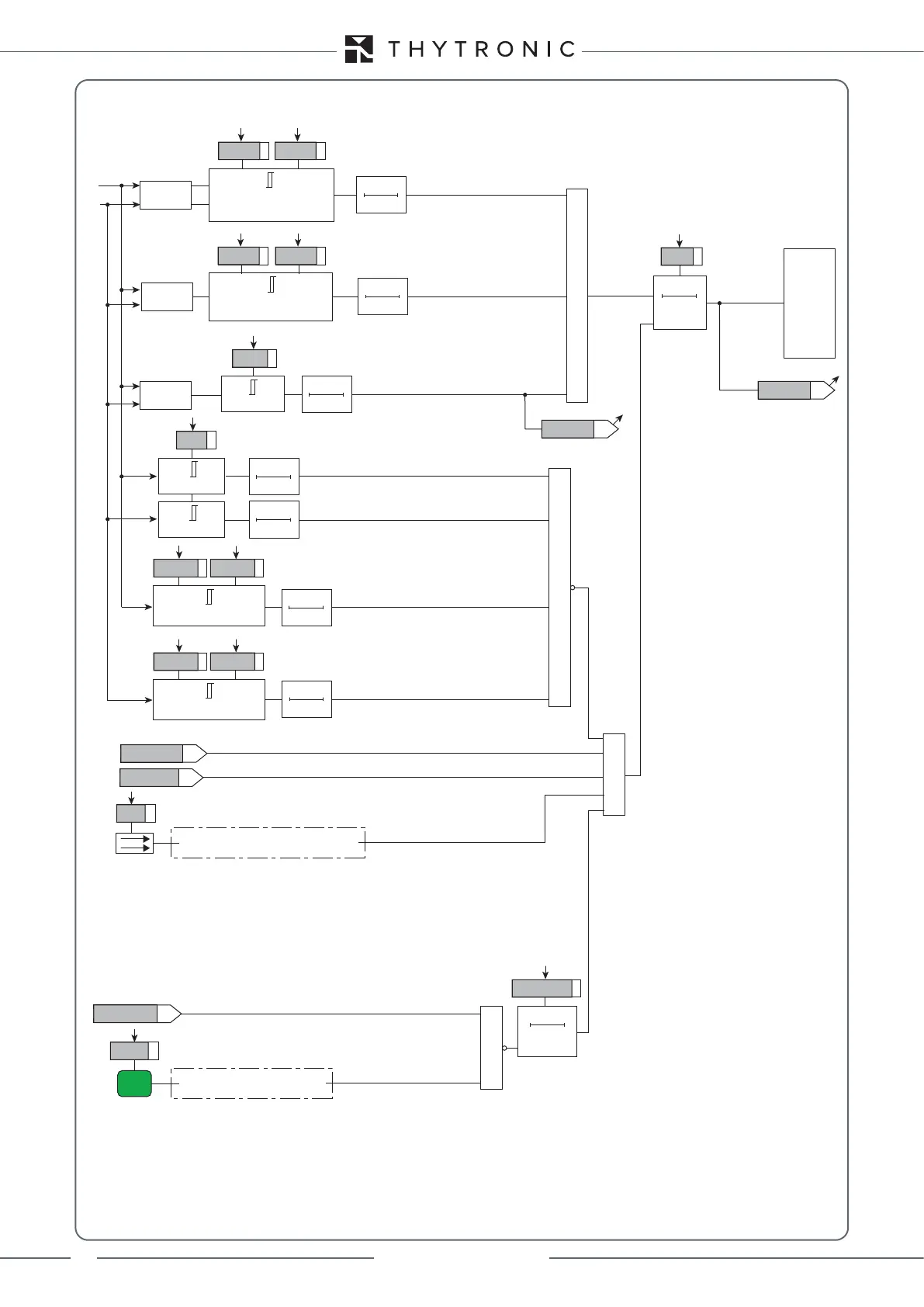
Functional diagram of the synchronisation check function (25) for synchronous grids
“1” with ∆f less than df-GRID (grids synchronous)
RESET
tSYNC
0T
tSYNC
∆f ≤ df-GRID
df-GRID
Rof>SYNC
“1” with unstable frequency measurement (block)
value ∆
(V1≥V2)
≥
&
TRIPPING MATRIX
(LED+RELAYS)
Sync
Sync-net
&
V1
V4
Sync-CK-K
Sync-CK-L
value ∆f
value ∆V
∆V ≤ dV12-SYNC
dV12-SYNC
dp12-SYNC
dp21-SYNC
dV21-SYNC
(V2≥V1)
∆V ≤ dV21-SYNC
tSTAB
0T
tSTAB
0T
tSTAB
0T
∆ ≤ dp12-SYNC
∆ ≤ dp21-SYNC
tSTAB
0T
tSTAB
0T
f1 = fn ± frange
frange
f2 = fn ± frange
tSTAB
0T
tSTAB
0T
“1” with V1 in the range Vmin-SYNC to Vmax-SYNC
“1” with f1 in the range (fn - frange) and (fn + frange)
“1” with ∆V less than the threshold
“1” with ∆ less than the threshold
“1” with f2 in the range (fn - frange) and (fn + frange)
“1” with V4 in the range Vmin-SYNC to Vmax-SYNC
Vmin-SYNC
Vmin-SYNC ≤ V1 < Vmax-SYNC
Vmax-SYNC
Vmin-SYNC
Vmin-SYNC ≤ V4 < Vmax-SYNC
Vmax-SYNC
74VT
≥
Reclosing
Reclosing sequence started by internal command (MMI or comms)
52a
Binary input INx
“1” with breaker closed
Enable
Binary input INx
“1” with button enabled
timeout-SYNC
timeout-SYNC
0T
RESET
CH