89
DMC3S - Manual - 08 - 2021
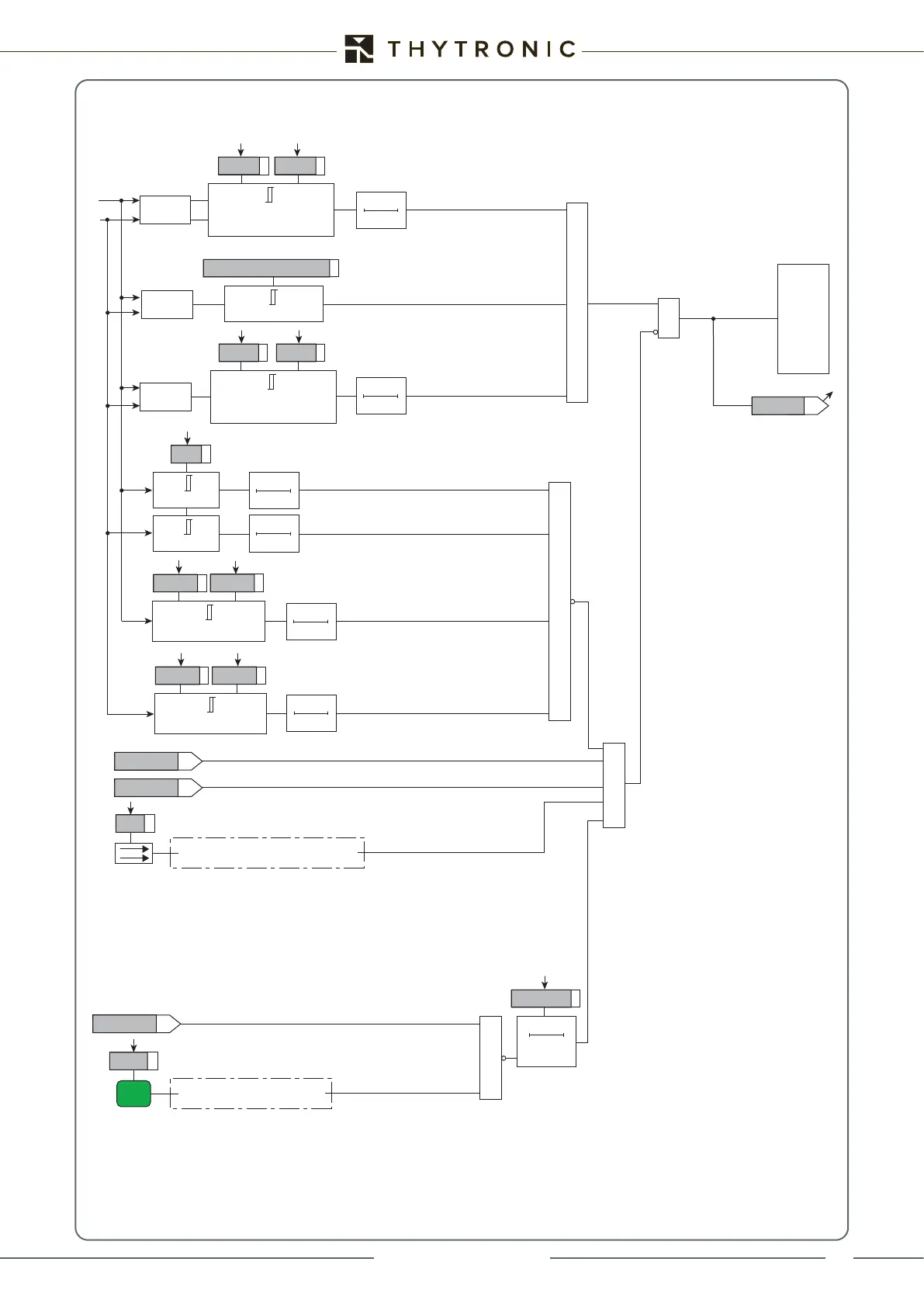
Functional diagram of the synchronisation check function (25) for asynchronous grids
∆ A- ≤ ∆ ≤ ∆ A+
A = 360 ∙ (tCB-CLOSE + tMEAS) ∙ ∆f
Rof>SYNC
74VT
“1” with unstable frequency measurement (block)
value
≥
≥
&
TRIPPING MATRIX
(LED+RELAYS)
Sync
&
&
Sync-CK-K
Sync-CK-L
value f
∆f-14 ≤ df14-SYNC
df14-SYNC
df41-SYNC
∆f-41 ≤ df41-SYNC
(f1≥f4)
(f4≥f1)
Reclosing
Reclosing sequence started by internal command (MMI or comms)
52a
Binary input INx
“1” with breaker closed
Enable
Binary input INx
“1” with button enabled
tSTAB
0T
tSTAB
0T
tSTAB
0T
timeout-SYNC
timeout-SYNC
0T
RESET
tSTAB
0T
tSTAB
0T
“1” with V1 in the range Vmin-SYNC to Vmax-SYNC
“1” with f1 in the range (fn - frange) and (fn + frange)
“1” with ∆f less than the threshold
“1” with ∆ less than the threshold
“1” with f2 in the range (fn - frange) and (fn + frange)
“1” with V2 in the range Vmin-SYNC to Vmax-SYNC
(V1≥V4)
V1
V4
value ∆V
∆V ≤ dV14-SYNC
dV14-SYNC
dV41-SYNC
(V4≥V1)
∆V ≤ dV41-SYNC
tSTAB
0T
f1 = fn ± frange
frange
f2 = fn ± frange
Vmin-SYNC
Vmin-SYNC ≤ V1 < Vmax-SYNC
Vmax-SYNC
Vmin-SYNC
Vmin-SYNC ≤ V4 < Vmax-SYNC
Vmax-SYNC
CH