FUNCTION CHARACTERISTICS
32
NC020 - Manual - 05 - 2022
— Undercurrent - 37
Preface
One fix operation threshold with fix delay and definite time characteristic and one adjustable thresh-
old.
The 37 elements are based on RMS measurement of three phase currents (the computed RMS value
takes into account the contribution of fundamental and harmonics). The first threshold is an internal
element servicing the Timer Discharge (TD) function.
Operation and settings
The RMS phase currents I
L1RMS
, I
L2RMS
, I
L3RMS
(including harmonics up to twenty-third order) are
compared with the threshold.
A start of the first element (I<) is issued when at least one of the three currents goes down the
threshold (0.1 I
n -
OR logic); after expiry of the associated operate time a command is issued to start
the discharge timer (TD); if instead the currents exceed the threshold, the element is restored.
The start and trip logic of the second element (I<<) may be selected OR or AND.
With OR selection, a start is issued when at least one of the three currents goes down the adjust-
able threshold (START); with AND selection, a start is issued when all the three currents go down
the adjustable threshold.
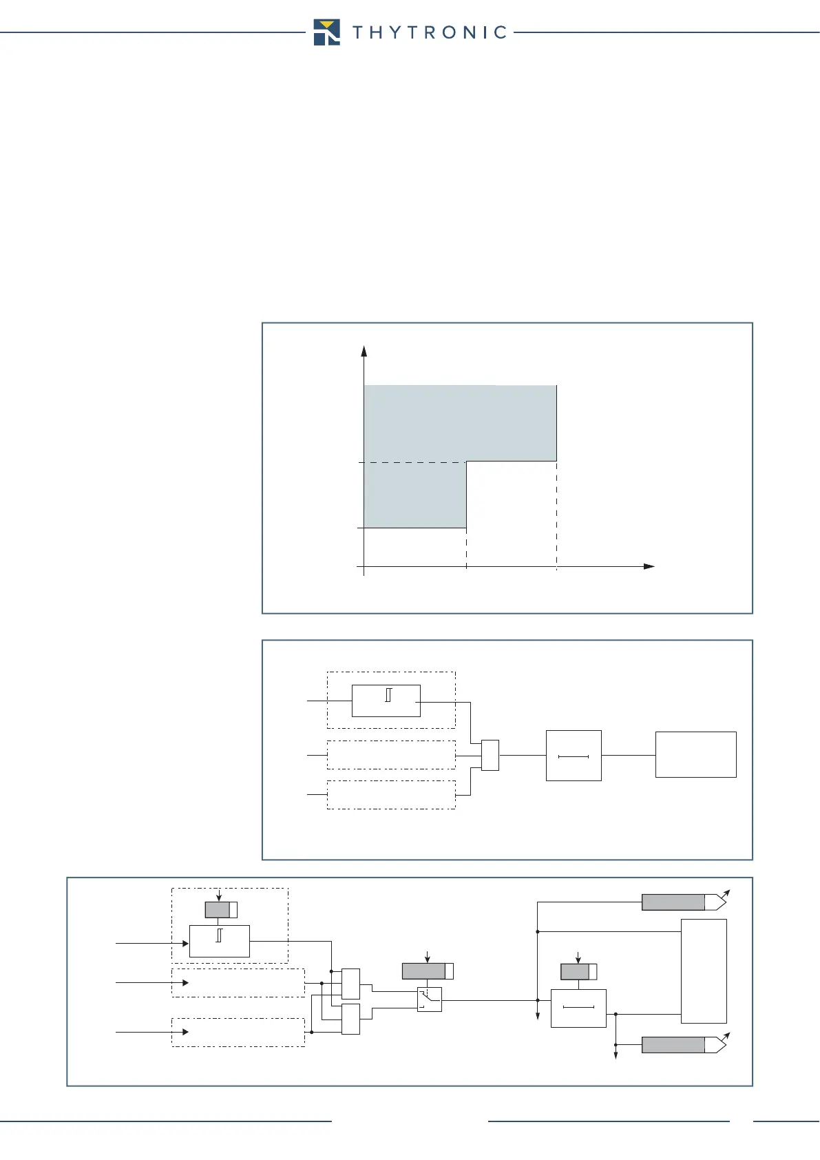
General operation of the undercurrent element - 37
t-int-F37.ai
I
RMS
t
TRIP
0.100
I
n
I<<
t<<
0.100 s
Fun-F37_S1.ai
First element undercurrent element - logic diagram
TD Discharge
timer
I<TR
≥1
I
L1RMS
I
L2RMS
I
L3RMS
I
L1RMS
≤
0.100
I
n
0T
0.100 s
Fun-F37_S2.ai
t
<<def
0T
TRIPPING MATRIX
(LED+RELAYS)
t
<<def
Start I<<
I<<ST-K
I<<TR-K
START-L
TRIP-L
Trip I<<
I<<deflogic
≥1
&
I
L1RMS
≤
I<<
def
I<<
def
I
L1RMS
I
L2RMS
I
L3RMS
Second element undercurrent element - logic diagram