FUNCTION CHARACTERISTICS
33
NC020 - Manual - 05 - 2022
— TD Discharge time
Preface
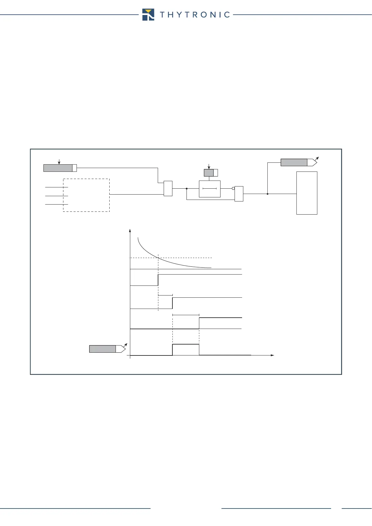
The discharge timer may be enabled or disabled.
When enabled it is started by the threshold of the undercurrent protection.
One or more output relay can be allocated; the LED 5 turns ON when the timer expires.
The reconnection inhibit output signal will be active until the set time has elapsed and is used to
inhibit the reconnection of a charged capacitor bank to a live network and limit the inrush current.
During the timer counting:
• The selected output relays and/or LED are driven
• The manual closing operation of the circuit breaker is inhibited.
• The MMI message “CAPACITOR DISCHARGE IN PROGRESS xxx s” is displayed,
where xxxx is the actual value of remaining discharge time in seconds, (the initial value is the cor-
responding threshold set by TD decreased with resolution of 1 s to 0). When the discharge timer
expires, the display message is automatically removed.
The actual value of remaining discharge time can be cleared (and the timer count of discharging TD
forced at the end of time) from keyboard or serial communication. This can be useful during commis-
sioning tests to remove the inhibition at closing of circuit breaker capacitor bank.
TD.ai
I
L1RMS
I
L2RMS
I
L3RMS
t
D
0T
TD Dscharge
TD Dscharge
ON≡Enable Discharge timer
&
&
TRIPPING MATRIX
(LED+RELAYS)
TD-P37 Enable
Trip I<
Delay timer
T
D
output
Start
I<
min[I
L1RMS,
I
L2RMS
I
L2RMS
]
t
t
D
TD-K
LED 5
t
D
Discharge timer (TD) - logic diagram
I<TR
I< Element
0.100 I
n
0.100 s