FUNCTION CHARACTERISTICS
39
NC020 - Manual - 05 - 2022
— Fundamental phase overcurrent - 50/51
Preface
Two operation thresholds, independently adjustable (I>>, I>>>) with adjustable delay (t>>, t>>>).
The first one may be programmed with definite or inverse time according the IEC 60255-3/BS142/IEEE
standards.
The second threshold has a definite time characteristic.
A reset time can be set (t
>>RES
, t
>>>RES
) useful to reduce the clearing time for intermittent faults.
Operation and settings
Each phase fundamental frequency current is compared with the setting value. Currents above the
associated pickup value are detected and a start is issued. After expiry of the associated operate
time a trip command is issued; if instead the current drops below the threshold, the element is re-
stored.
The I>> threshold may be programmed with definite or inverse time according the following char-
acteristic curves:
• Standard Inverse Time (IEC 255-3/BS142 type A or SIT): t = 0.14 · t>>
inv
/ [(I/I>>
inv
)
0.02
- 1]
• Very Inverse Time (IEC 255-3/BS142 type B or VIT): t = 13.5 · t >>
inv
/ [(I/I>>
inv
) - 1]
• Extremely Inverse Time (IEC 255-3/BS142 type C or EIT): t = 80 · t>>
inv
/ [(I/I>>
inv
)
2
- 1]
• Moderately Inverse (ANSI/IEEE type MI): t = t>
inv
· {0.01 / [(I/I>>
inv
)
0.02
- 1] + 0.023}
• Very Inverse (ANSI/IEEE type VI): t = t>>
inv
· {3.922 / [(I/I>>
inv
)
2
- 1] + 0.098}
• Extremely Inverse (ANSI/IEEE type EI): t = t >>
inv
· {5.64 / [(I/I>>
inv
)
2
- 1] + 0.024}
Where:
t: operate time
I>>
inv
: threshold setting
t>>
inv
: operate time setting
For all inverse time characteristics, following data applies:
• Asymptotic reference value (minimum pickup value): 1.1 I>>
inv
• Minimum operate time: 0.1 s
• Range where the equation is valid:
[1]
1.1 ≤ I/I>>
inv
≤ 20
For all definite time elements the upper limit for measuring is 40 I
n
.
All overcurrent elements can be enabled or disabled by setting the relative start and/or trip output to
a selectable relay inside the Set \ Relays menu.
The I>>overcurrent element can be programmed with inverse time characteristic by setting the
I>>Curve parameter (DEFINITE, IEC/BS A, IEC/BS B, IEC/BS C, ANSI/IEE MI, ANSI/IEE
VI, ANSI/IEE EI) available inside the Set \ 50-51 \ I>> Setpoints menu.
An adjustable reset time delay is provided for second and third threshold (t
I
>>
RES
, t
I
>>>
RES
).
Note 1 When the input value is more than 20 times the set point , the operate time is limited to the value corresponding to 20 times the set point
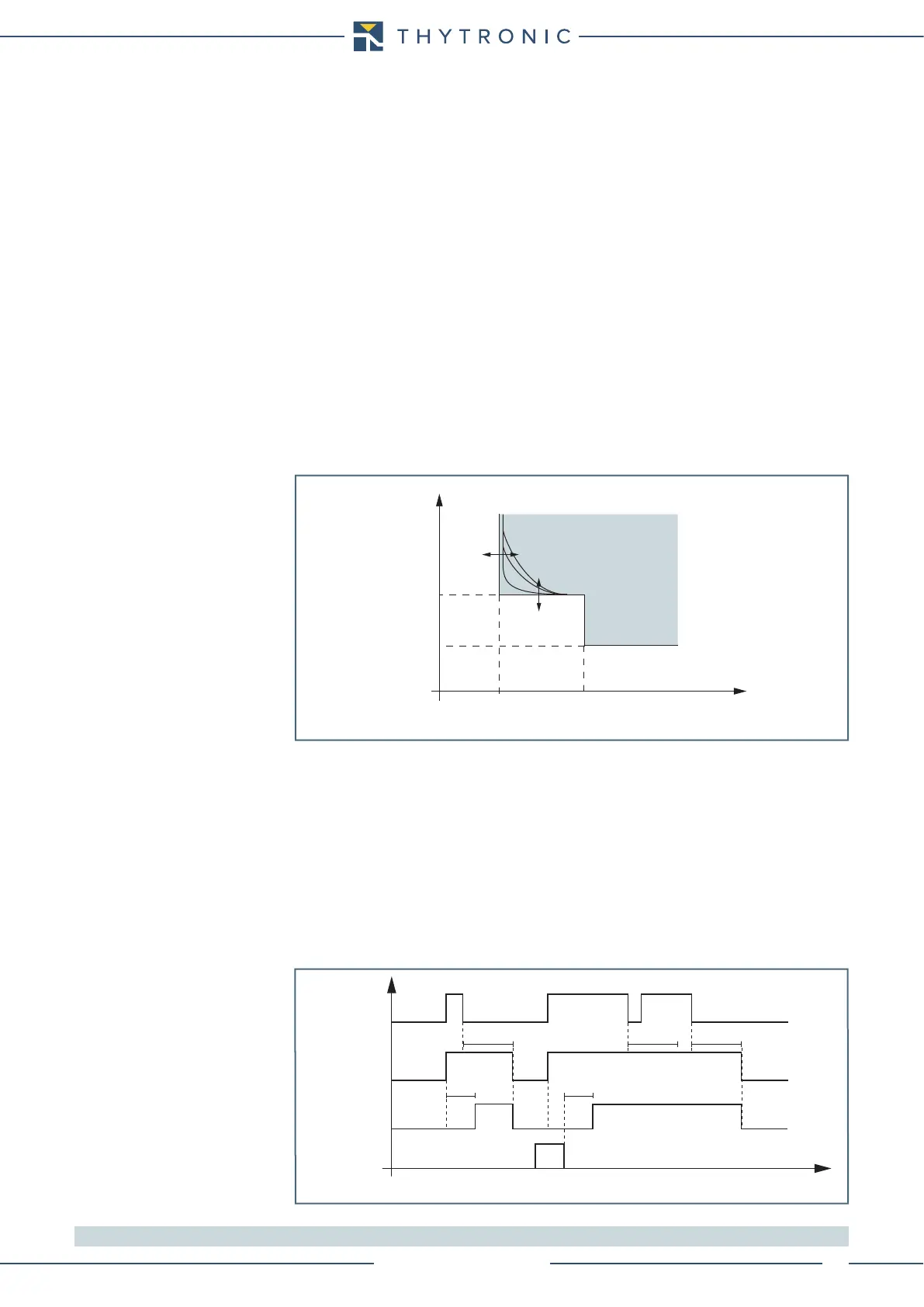
t-int-F50-51-S2S3.ai
I
I>> I>>>
t>>
t>>>
t
t-int-F46N.ai
I
NC
I
N
> I
N
>>
t
N
>
AL
t
N
>
t
N
>>
I
N
>
AL
t
TRIP
General operation time characteristic for the neutral unbalance elements - 46N
TRIP
General operation time characteristic for the fundamental phase overcurrent elements - 50/51
I>> Start
I>> Trip
t>> t>>
RESET
INPUT >> threshold
t
I
>>
RES
t
I
>>
RES
t
I
>>
RES
t
I>> element fundamental phase overcurrent timers - 50/51