FUNCTION CHARACTERISTICS
38
NC020 - Manual - 05 - 2022
Breaker failure (BF)
The elements (I>) can produce the Breaker Failure output if the Trip I> output is set for BF Enable.
The outputs are available inside the Set \ Breaker failure menu.
[1]
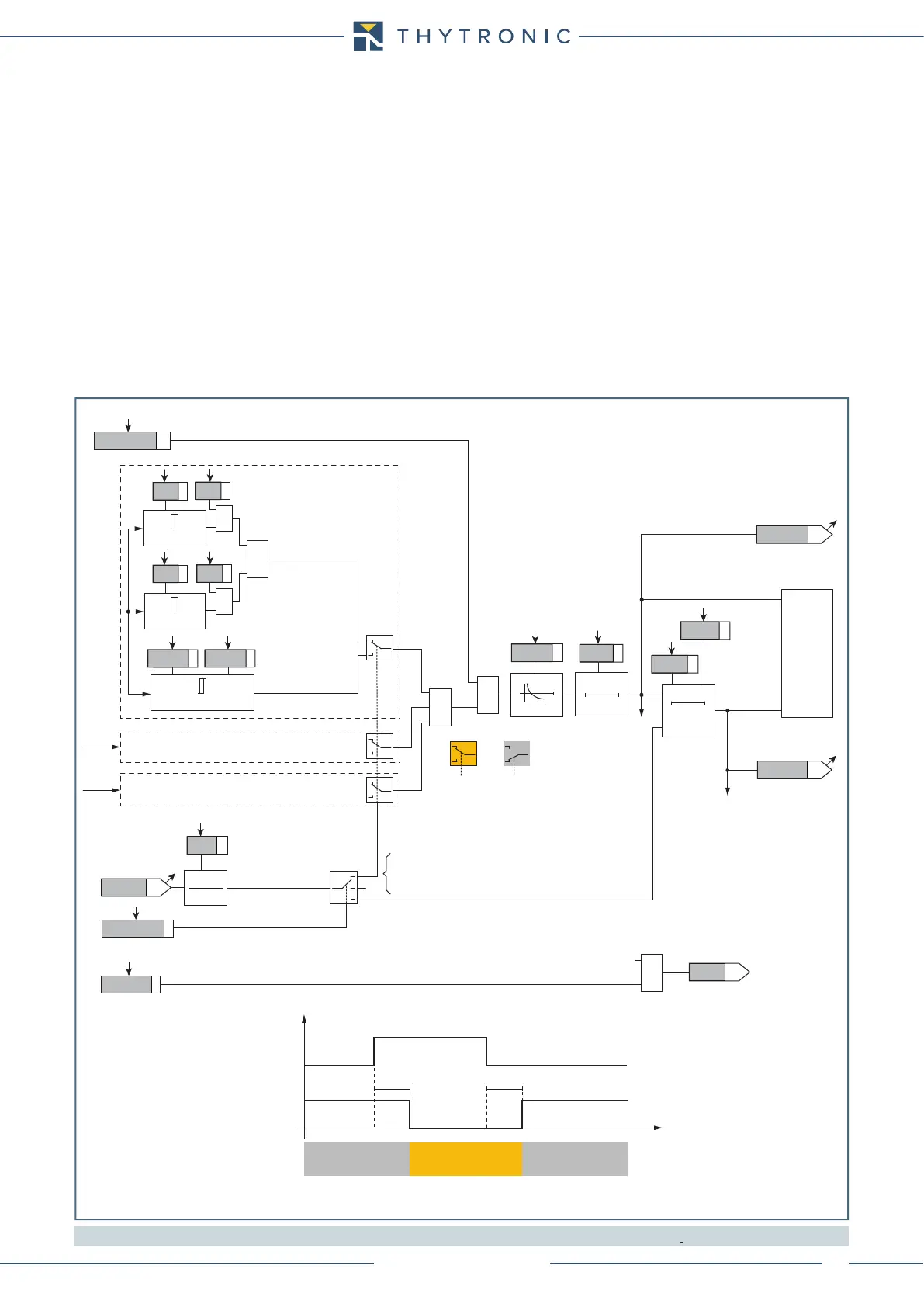
Cold load pickup
If the CLP function (Cold Load Pick-up) is enabled for element blocking, the selected threshold may
be blocked for an adjustable time interval, starting from the circuit breaker closure.
This operating mode may be select by setting ON-Blocking the ICLP> parameter.
If the CLP function (Cold Load Pick-up) is enabled for threshold change, the selected threshold may
be changed for an adjustable time interval, starting from the circuit breaker closure.
This operating mode may be select by setting ON-Changing the ICLP> parameter, whereas the
operating thresholds within the CLP may be adjusted inside the Set \ 50/51 RMS \ I> Element \ I>
Setpoint menu.
For both operating modes the CLP Activation time parameters (tCLP>) may be adjusted inside the
Set \ 50/51 RMS \ I> Element \ I> Setpoint menu.
Note 1 The common settings concerning the Breaker failure protection are adjustable inside the Breaker Failure - BF menu.
Fun_50-51-RMS.ai
I
L1RMS
I
L2RMS
I
L3RMS
t
I
>
RES
T0
RESET
t
I
>
0T
≥1
≥1
t
I
>
def
t
I
>
inv
t
I
>
RES
Start I>
Trip I>
CB-State
ON≡Enable I> overcurrent element
(Pickup within CLP)
(Pickup outside CLP)
&
T 0
t
CLP>
ICLP>Mode
I
CLP
>def
t
CLP
>
I
CLP
>inv
ON≡Enable
BF Enable
towards BF logic
I> BF
&
Trip I>
TRIPPING MATRIX
(LED+RELAYS)
I> Curve
0T
A
B
C
A =“1”A =“0 or OFF”
Output
t
CLP>
I> Enable
t
CLP>
CB State CB OPEN CB CLOSED CB OPEN
Output t
CLP>
t
0.1 s
HIGH THRESHOLD/
BLOCK
LOW THRESHOLD/
UNBLOCK
HIGH THRESHOLD/
BLOCK
A = ON - Change setting
B = OFF
C = ON - Element blocking
I>TR-K
I>TR-L
I>ST-L
I>ST-K
&
State
I>
inv
I
L1RMS
≥
I>
def
I
L1RMS
≥
I>
inv
I
L1RMS
≥
I
CLP
>
(def/inv)
I>
def
&
State
RMS phase overcurrent (50/51 RMS) - First element logic diagram (I>)