FUNCTION CHARACTERISTICS
34
NC020 - Manual - 05 - 2022
— Neutral unbalance current - 46N
Preface
One alarm and two operation thresholds, independently adjustable with adjustable operating times.
Operation and settings
The unbalance current I
N
is used with:
• Fundamental component of the neutral unbalance current measured on the double star connection
as module.
• Displacement of the unbalance current I
N
, positive for lagging current compared with I
L1
current
I
N PHI
= (∠I
N
- ∠I
L1
) as phase displacement.
To compensate the inherent unbalance in a un-faulted three phase capacitor bank, a suitable auto-
matic adjustment is provided.
The compensation values (I
NC MOD calib
, I
NC PHI calib
) may be acquired when no fault are present on-
duty bank capacitors by executing the the command INC Comp exe available inside the Com-
mands \ Compensation \ Set compensation menu.
[1]
The relay internally measures the real unbalanced current when fault are present; the compen-
sated unbalance current phasor is calculated by protection relay by the vector difference
I
NC
= |I
N
I
N PHI
- I
NC MOD calib
I
N PHI calib
| where:
• I
N
is the RMS value of fundamental component of the unbalance current
• I
N PHI
is the displacement of the unbalance neutral current with respect to the I
L1
phasor
• I
NC MOD calib
is the module of the compensation unbalance neutral current
• I
NC PHI calib
is the displacement of the compensation unbalance neutral current with respect to the
I
L1
phasor
The calibration parameters (I
NC MOD calib
module and I
N PHI calib
phase) are available inside the Read
\ IN Compensation menu.
If the unbalance current I
NC
exceeds the setting threshold a start is issued. After expiry of the as-
sociated operate time a trip command is issued; if instead the current drops below the threshold, the
element is restored.
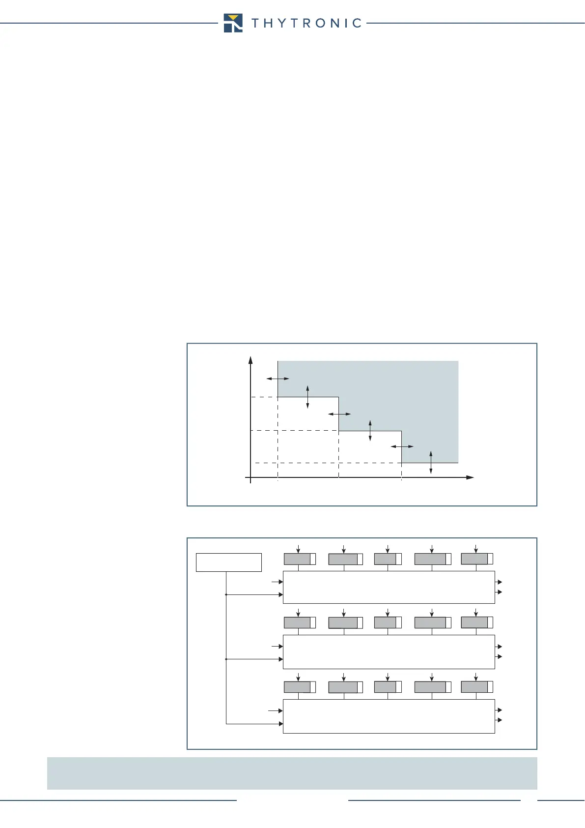
All the elements (I
N>AL
, I
N>
, I
N>>
) have definite time characteristic.
All overcurrent elements can be enabled or disabled by setting the relative start and/or trip output to
a selectable relay inside the Set \ Relays menu.
Note 1 Compensation is possible only if the following two conditions are satisfied:
- the IL1 phase current is greater than 0.1 In
- the RMS value of fundamental component of the unbalance current (I
N
) is less than 0.5 I
Nn
t-int-F46N.ai
I
NC
I
N
>
def
I
N
>>
def
t
IN
>
ALdef
t
IN
>
def
t
IN
>>
def
I
N
>
ALdef
t
TRIP
General operation time characteristic for the neutral unbalance elements - 46N
Compensation 46N
all-F46N.ai
General logic diagram of the unbalance current elements - 46N
I
N
I
C
I
N
IN>AL Element
Start IN>
AL
Trip IN>
AL
t
IN
>
ALdef
INCLP>
ALdef
IN>
ALdef
INCLP>
AL
tINCLP>
AL
I
N
I
C
I
C
IN> Element
Start IN>
Trip IN>
t
IN
>
def
INCLP>
def
IN>
def
INCLP>
tINCLP>
IN>> Element
Start IN>
Trip IN>
t
IN
>>
def
INCLP>>
def
IN>>
def
INCLP>>
tINCLP>>