FUNCTION CHARACTERISTICS
44
NC020 - Manual - 05 - 2022
— Peak 0vervoltage - 59H
Preface
The purpose is to protect the capacitor bank against peak overvoltage, due to fundamental and har-
monics currents, which may lead to dielectric breakdown.
The capacitor voltages are calculated from the three-phase line currents (fundamental frequency
component and harmonics up to twenty-third order) for any phase by means of arithmetic sum of
the relative voltage components without requiring the installation of VTs for the direct measurement
of the capacitor voltages.
Three operation thresholds, independently adjustable with adjustable delay are available.
All threshold operates with definite time characteristic.
Operation and settings
The calculated peak to peak voltage is compared with the setting values.
A start is issued when at least one of the three voltages overcomes the adjustable threshold; after
expiry of the associated operate time a trip command is issued; if instead the voltages go down the
threshold, the element is restored.
All elements can be enabled or disabled by setting the relative start and/or trip output to a selectable
relay inside the Set \ Relays menu.
An adjustable reset time delay is provided for every threshold t
U>RES
, t
U>>RES
, t
U>>>RES
).
Breaker failure (BF)
All elements can produce the Breaker Failure output if the Trip U>, Trip U>> and/or Trip U>>>
outputs are set for BF Enable. The outputs are available inside the Set \ Breaker failure menu.
[1]
Cold load pickup
If the CLP function (Cold Load Pick-up) is enabled for element blocking, the selected threshold may
be blocked for an adjustable time interval, starting from the circuit breaker closure.
This operating mode may be select by setting ON-Blocking the UCLP>, UCLP>> and/or
UCLP>>> parameters inside the Set \ 59H \ U>Element (U>>Element, U>>>Element) \ U>Setpoints
(U>> Setpoints, U>>> Setpoints) menus.
If the CLP function (Cold Load Pick-up) is enabled for threshold change, the selected threshold may
be changed for an adjustable time interval, starting from the circuit breaker closure.
This operating mode may be select by setting ON-Changing the UCLP>, UCLP>> and/or UCLP>>>
parameters inside the Set \ 59H \ U>Element (U>>Element, U>>>Element) \ U>Setpoints (U>> Setpoints,
U>>> Setpoints) menus, whereas the operating thresholds within the CLP may be adjusted inside the
Set \ 59H \ U>Element (U>>Element, U>>Element) \ U>Definite (U>>Definite, U>>>Definite) menus.
For both operating modes the CLP Activation time parameters (tUCLP, tUCLP>>, tUCLP>>>) may
be adjusted inside the Set \ 59H \ U>Element (U>>Element, U>>>Element) \ U>Setpoints (U>> Set-
points, U>>> Setpoints) menus.
Note 1 The common settings concerning the Breaker failure protection are adjustable inside the Breaker Failure - BF menu.
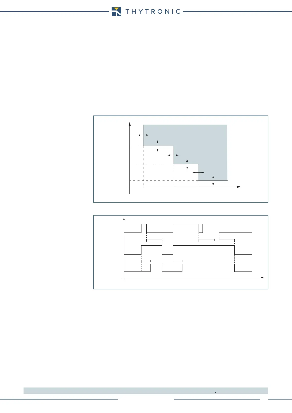
U
t
U
>
def
U>
def
U>>
def
t
U
>>
def
t
t
U
>>>
def
U>>>
def
TRIP
General operation time characteristic for the peak overvoltage elements - 59H
Timers-F59H.ai
U> element - 59H - peak overvoltage timers
U> Start
U> Trip
t
U>def
t
U>def
U ≥ threshold
t
U
>
RES
t
U
>
RES
t
U
>
RES
t