FUNCTION CHARACTERISTICS
42
NC020 - Manual - 05 - 2022
— Residual overcurrent - 50N/51N
Preface
The residual current is calculated by the vector sum of the three phase currents.
Two operation thresholds, independently adjustable with adjustable delay.
For each threshold a reset time can be set useful to reduce the clearing time for intermittent faults.
Operation and settings
The residual fundamental frequency current is compared with the setting value. Current above the
associated pickup value is detected and a start is issued. After expiry of the associated operate time
a trip command is issued; if instead the current drops below the threshold, the element is restored.
For all elements the upper limit for measuring is 40 I
n
.
All elements can be enabled or disabled by setting the relative start and/or trip output to a selectable
relay inside the Set \ Relays menu.
An adjustable reset time delay is provided for every threshold t
IE>RES
, t
IE>>RES
).
Breaker failure (BF)
The elements (I
E
>, I
E
>>) can produce the Breaker Failure output if the Trip IE> and/or Trip IE>
outputs are set for BF Enable. The outputs are available inside the Set \ Breaker failure menu.
[1]
Cold load pickup
If the CLP function (Cold Load Pick-up) is enabled for element blocking, the selected threshold may
be blocked for an adjustable time interval, starting from the circuit breaker closure.
This operating mode may be select by setting ON-Blocking the IECLP> and/or IECLP>> param-
eters inside the Set \ 50N-51N \ IE>Element (IE>>Element) \ IE>Setpoints (IE>> Setpoints) menus.
If the CLP function (Cold Load Pick-up) is enabled for threshold change, the selected threshold may
be changed for an adjustable time interval, starting from the circuit breaker closure.
This operating mode may be select by setting ON-Changing the IECLP> and/or IECLP>>
parameters inside the Set \ 50N-51N \ IE>Element (IE>>Element) \ IE>Setpoints (IE>> Setpoints)
menus, whereas the operating thresholds within the CLP may be adjusted inside the Set \ 50N-51N
\ IE>Element (IE>>Element) \ IE>Definite ( IE>>Definite ) menus.
For both operating modes the CLP Activation time parameters (tIECLP, tIECLP>>) may be ad-
justed inside the Set \ 50N-51N \ IE>Element (IE>>Element ) \ IE>Setpoints (IE>> Setpoints) menus.
Note 1 The common settings concerning the Breaker failure protection are adjustable inside the Breaker Failure - BF menu.
I
EC
t
E
>
def
I
E
>
def
I
E
>>
def
t
E
>>
def
t
TRIP
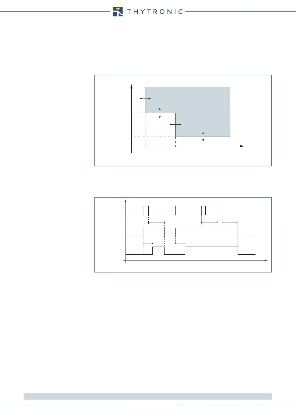
General operation time characteristic for the residual overcurrent elements - 50N/51N
Timers-F50N-51N.ai
IE> element - 50N/51N - residual overcurrent timers
IE> Start
IE> Trip
t
IE>def
t
IE>def
I
EC
≥ threshold
t
IE>RES
t
IE>RES
t
IE>RES
t