FUNCTION CHARACTERISTICS
50
NC020 - Manual - 05 - 2022
— Test
The test function allows the checking of each output relay and/or LED
In cases involving selection of the test mode without any changes in the status of the output relays,
upon tripping of the selected threshold, the corresponding LED is lit and the test outcome recorded
as the most recent event. The test condition is shown by means of the blinking green LED ON.
[1]
• Test I> no-TR
• Test I>> no-TR
• Test I>>> no-TR
• Test IE> no-TR
• Test IE>> no-TR
• Test IN>AL no-TR
• Test IN> no-TR
• Test IN>> no-TR
• Test U> no-TR
• Test U>> no-TR
• Test U>>> no-TR
• Test I<< no-TR
In cases involving selection of the test mode with changes in the status of the output relays the
corresponding programmed output relay is switched, the corresponding LED lit and the outcome re-
corded as the most recent event. The test condition is shown by means of the blinking green ON.
[2]
• Test I> TR
• Test I>> TR
• Test I>>> TR
• Test IE> TR
• Test IE>> TR
• Test IN>AL TR
• Test IN> TR
• Test IN>> TR
• Test U> TR
• Test U>> TR
• Test U>>> TR
• Test I<< TR
For both modes the test may be ended by means of the Test o command; in any case they are
closed after 2 minutes.
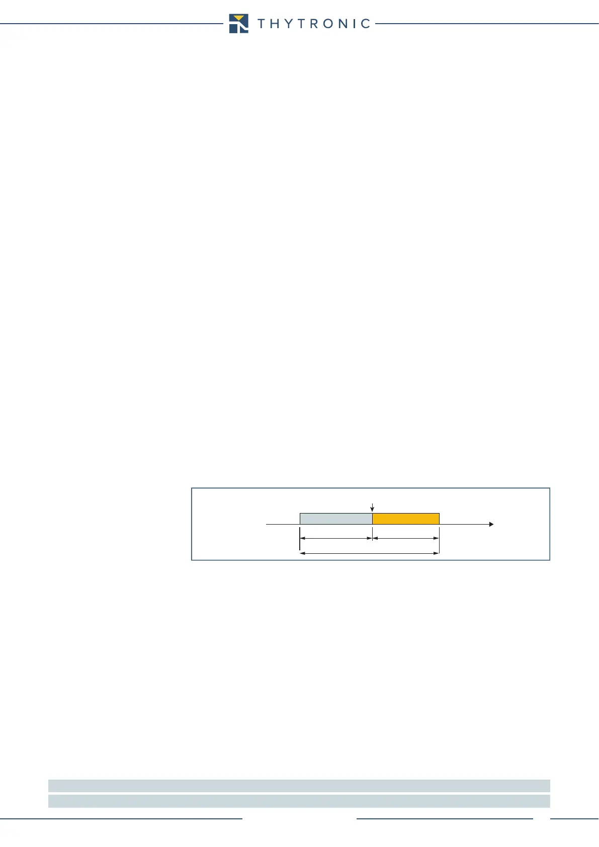
— Oscillography
Set trigger
Following parameters, available inside the Oscillography \ Setting menu, are user-programmable:
• Pre-trigger time.
• With setting of the Trigger parameter General start or General trip the recording starts with
state change of any protection elements.
• With setting of the Trigger parameter Manual the recording starts with manual command (Thy-
Visor).
• With setting of the Trigger parameter K1...K4 the recording starts with state change of the se-
lected output relay.
• With setting of the Trigger parameter IN1, IN2, IN3 he recording starts with state change of
any binary input.
• With setting of the rigger aux parameter Start I>, Start I>>, Start I>>>,.... the recording
starts with state change of start or trip of the selected protection element.
Set measured channels
The analog measures (i
L1
, i
L2
, i
L3
, i
N
) may be select inside the Oscillography \ Setting \ Analog chan-
nel 1...4 menu.
Everyone of four analog channel may be associated to one of the selected measures.
Set digital channels
The desired I/O signals may be select inside the Oscillography \ Setting \ Digital channels menu
(General start, General trip, K1... K4, , IN1, IN2, IN3).
Note 1 The test is performed (LED) even if the concerning element is assigned to almost one output relay
Note 2 The test is performed (LED & relays) even if the concerning element is assigned to almost one output relay
trigger.ai
Trigger
Time
pre-trigger
record length
post-trigger
0...63 T