FUNCTION CHARACTERISTICS
35
NC020 - Manual - 05 - 2022
Breaker failure (BF)
The elements (I
N
>
AL
, I
N
>, I
N
>>) can produce the Breaker Failure output if the Trip IN>AL, Trip IN>
and/or Trip >> outputs are set for BF Enable. The outputs are available inside the Set \ Breaker
failure menu.
[1]
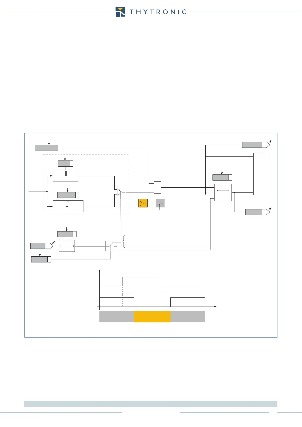
Cold load pickup
If the CLP function (Cold Load Pick-up) is enabled for element blocking, the selected threshold may
be blocked for an adjustable time interval, starting from the circuit breaker closure.
This operating mode may be select by setting ON-Blocking the INCLP>AL, INCLP> and/or IN-
CLP>> parameters inside the Set \ 46N \ IN>AL Element (IN>Element , IN>>Element ) \ IN>AL Set-
points (IN> Setpoints, IN>> Setpoints) menus.
If the CLP function (Cold Load Pick-up) is enabled for threshold change, the selected threshold may
be changed for an adjustable time interval, starting from the circuit breaker closure.
This operating mode may be select by setting ON-Changing the INCLP>AL, INCLP>and/or IN-
CLP>> parameters inside the Set \ 46N \ IN>AL Element (IN>Element , IN>>Element ) \ Setpoints
menus, whereas the operating thresholds within the CLP may be adjusted inside the Set \ 46N \
IN>AL Element (IN>Element , IN>>Element ) \ IN>AL Definite (IN>Definite , IN>>Definite ) menus.
For both operating modes the CLP Activation time parameters (tINCLP-AL, tINCLP>, tINCLP>>)
may be adjusted inside the Set \ 46N \ IN>AL Element (IN>Element , IN>>Element ) \ IN>AL Setpoints
(IN> Setpoints, IN>> Setpoints) menus.
Note 1 The common settings concerning the Breaker failure protection are adjustable inside the Breaker Failure - BF menu.
46NAL.ai
I
NC
RESET
t
IN>ALdef
0T
Start IN>AL
Trip I>AL
CB-State
ON≡Enable IN>AL unbalance current element
(Pickup within CLP)
(Pickup outside CLP)
&
T 0
t
INCLP>AL
INCLP>AL
I
NCLP
>
AL
def
t
INCLP>AL
TRIPPING MATRIX
(LED+RELAYS)
A
B
C
A =“1”A =“0 or OFF”
Output
t
INCLP>AL
IN>AL Enable
t
INCLP>
CB State CB OPEN CB CLOSED CB OPEN
Output t
NCLP>
t
0.1 s
HIGH THRESHOLD/
BLOCK
LOW THRESHOLD/
UNBLOCK
HIGH THRESHOLD/
BLOCK
A = ON - Change setting
B = OFF
C = ON - Element blocking
IN>ALTR-K
LED 2
IN>ALST-L
IN>ALST-K
I
NC
≥
I
N
>
ALdef
I
N
>
ALdef
I
NC
≥
I
NCLP
>
AL
def
t
IN>ALdef
Neutral unbalance current (46N) - Alarm element logic diagram (IN>
AL
)