INSTALLATION
58
NC020 - Manual - 05 - 2022
CT amperometric inputs
The amperometric input circuits are assembled inside the fixed module, so no short circuit on the
secondary CTs must be provided when the removable module is pulled out
In the event of case replacement, some camps must be provided externally to shorting the second-
ary CTs circuits to avoid secondary open circuit of CTs that may endanger equipment or people.
When making the current connections, attention must be paid to not exceeding the performance
of the line current transformers. To be exact, the total load, constituted by the protective relay, any
other protective relays or measuring instruments and the resistance of the connections, must not ex-
ceed the line CT performance. In particular, consumption of the relay input circuit must not exceed
0.2 VA while the load (expressed in VA) constituted by the conductors is given by:
0.018 × L × I
n
2
/ S
where:
L the overall length, expressed in m, of the two conductors in relation to each phase;
I
n
nominal current of the line CT expressed in A;
S cross sectional area of the current conductors expressed in mm
2
.
It is recommended that cabling of a suitable thickness be used in order to limit wear of the CT sec-
ondary circuits.
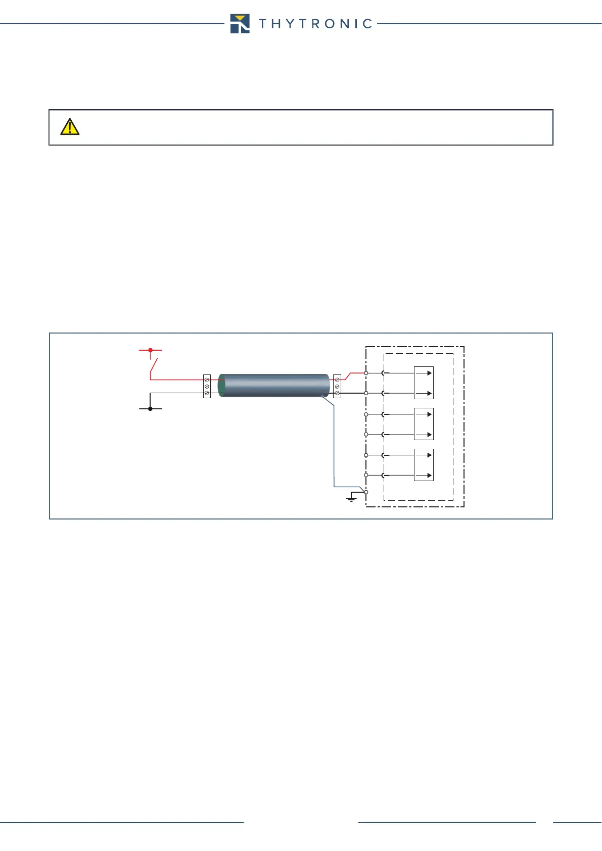
Binary inputs
The dry input circuits, despite being galvanically isolated, must preferably be supplied with the same
auxiliary voltage of the control panel.
The inputs are polarity free with wide voltage range.
The optocupled inputs are immune to transitory interferences, however the following recommenda-
tion must be considered in high disturbed environments:
• Position input wiring away from high energy sources.
• Use shielded cables with ground connection on only one end (preferably at the relay side.
Output relays
Four output relays are available (SPDT, type C):
• K1, K2 and K4 (trip relays).
• K3 (signalling relay).
It is advisable to verify that the technical characteristic of the contacts be suitable for the applied
load (about current, nominal voltage, make and break current , etc..).
All contacts are shown in de-energized state for standard reference
In case of disconnection CT wiring to the case, pay attention must to do not open live circuits.
CAUTION
+UAUX
-UAUX
A13
A14
IN1
A B
A15
A16
IN2
A17
A18
IN3