10-1
OM_2GX/AERO X_0413RevA
2GX/AERO X Owner’s Manual
CHAPTER 10: WHEEL LOCKS
I WARNING
TiLite recommends that you remove the wheel locks from your chair frame prior to engaging in any sport.
If you ignore this
Warning, you may seriously injure yourself or others or damage the wheelchair.
I WARNING
The wheel stop must embed into the tire at least 3/16” or the chair may roll unexpectedly. Therefore, before adjusting the
lock you must inate the tires to the recommended tire pressure (see sidewall of the tire). If you adjust the locks when the
tires are under-inated, the lock will not operate properly when the tire is fully inated.
If you ignore this Warning, you may
fall, tip over or lose control of the wheelchair and seriously injure yourself or others or damage the wheelchair.
I WARNING
After adjusting the wheel locks, engage the wheel locks and push against the tires to verify that the wheel locks prevent
the wheels from moving. If not, readjust the wheel locks until the wheel locks securely prevent the chair from rolling.
If you
ignore this Warning, you may fall, tip over or lose control of the wheelchair and seriously injure yourself or others or damage
the wheelchair.
Compact Push to Lock
Adjusting
Tools Needed:
• 3/16” Allen Wrench
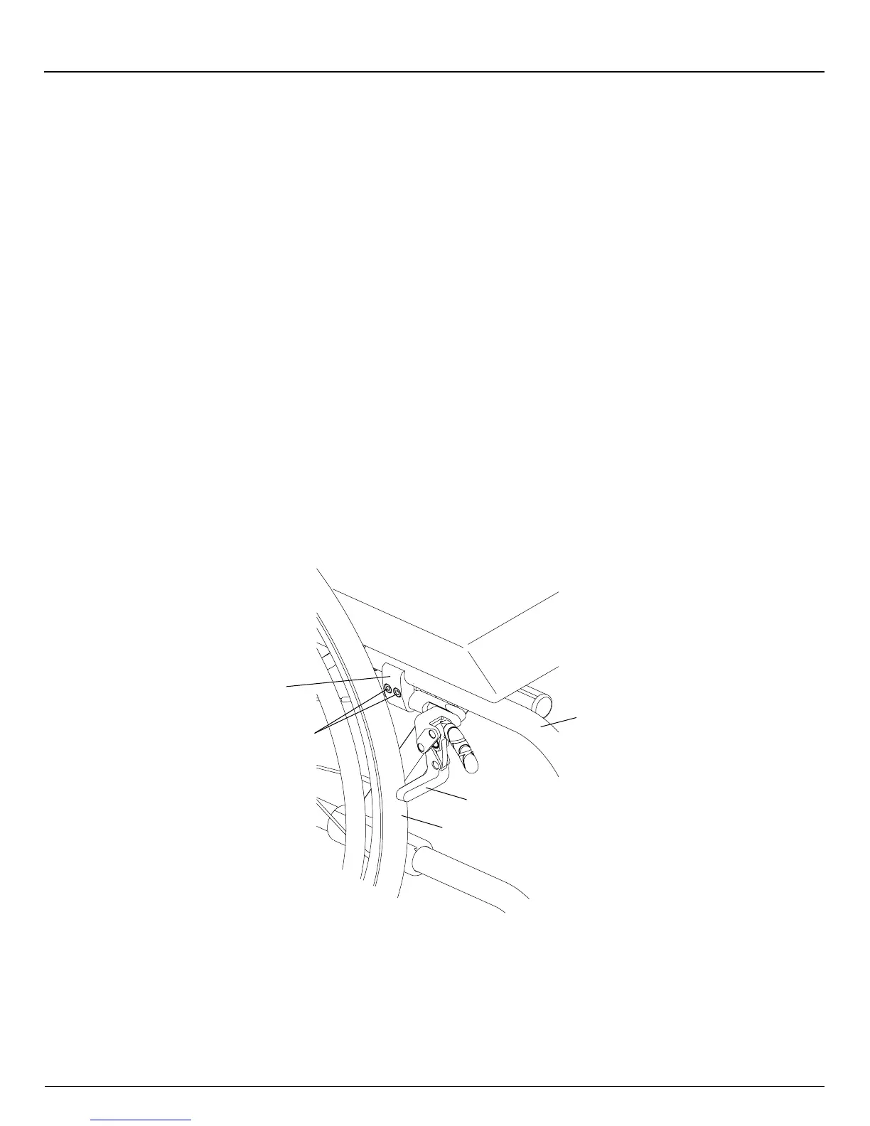
1. Loosen, but do not remove, the Allen screws in the wheel lock clamp. See Figure 10-1.
2. Adjust the position of the wheel lock clamp on the frame so the wheel stop embeds at least 3/16” into the tire when
engaged in the locked position.
3. Securely tighten the two Allen screws that secure the wheel lock clamp to the frame.
Figure 10-1
Adjusting/Replacing
Wheel
Lock
Clamp
Frame
Wheel
Stop
Tire
Allen
Screws
Replacing
Tools Needed:
• 3/16” Allen Wrench
1. Loosen, but do not remove, the two Allen screws that secure the wheel lock clamp to the frame. See Figure 10-1.
2. Slide the wheel lock out of the clamp.
3. Slide the new wheel lock into the wheel lock clamp, but do not tighten the Allen screws.
4. Follow the procedures under “Compact Push to Lock - Adjusting” on page 10-1 to position and secure the new wheel
lock.