21
9. Flow Viewer
This section explains about the Flow Viewer.
In the Flow Viewer a box is displayed to indicate the signal-processing functions of the unit and a
graphical representation of the unit's signal-processing flow, showing each signal flow as a
straight line connecting input and output.
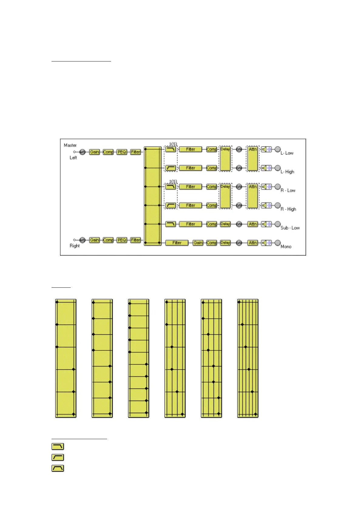
The figure below is one example of the unit with a 2-input/6-output configuration.
The signal-processing functions of each box are presented below.
Matrix
2 in 6 out 2 in 8 out 2 in 10 out 4 in 6 out 4 in 8 out 6 in 6 out
Crossover (Xover)
← Low-Pass Filter
← High-Pass Filter
← Band-Pass Filter(Low-Pass Filter + High-Pass Filter)
 Loading...

