Do you have a question about the Toa FV-200RF-AS and is the answer not in the manual?
Details critical safety measures for installing the equipment to prevent hazards.
Outlines essential safety guidelines for operating the equipment to avoid injury or damage.
Provides a visual representation of the system's main components and their interconnections.
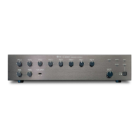
Details the front panel controls and indicators of the FV-200EV-AS unit.
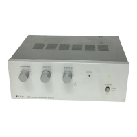
Explains the front panel controls and indicators of the FV-200PP-AS unit.
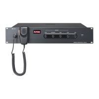
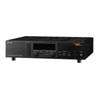
Covers the front and rear panel components of the FV-200RF-AS unit.
Explains the front and rear panels of the FV-200CA-AS unit for amplifier changeover.
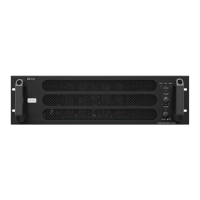
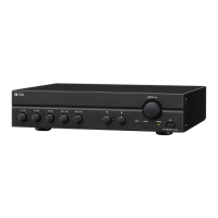
Details the front and rear panels of the FV-224PA-AS power amplifier.
Describes the front and rear panels of the FV-248PA-AS series power amplifiers.
Covers the nomenclature and functions of the RM-200M remote microphone.
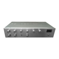
Details the front and rear panels of the FV-200PS-AS DC power supply.
Provides instructions for installing panels into a cabinet rack and rack clearance.
Step-by-step guide for wall-mounting the RM-200M remote microphone.
Step-by-step guide for installing the VP-200VX module into power amplifiers.
Illustrates the overall system wiring and component connections.
Details how to expand the 24V DC power supply for system growth.
Illustrates connecting amplifiers for automatic fault changeover using FV-200CA-AS.
Guidelines for using UPS and VX-2000DS for emergency power backup.
Describes how to initiate and manage emergency broadcasts manually or automatically.
Provides step-by-step procedures for operating the system during emergencies.
| Output Power | 200 W |
|---|---|
| Signal-to-Noise Ratio | 60 dB or more |
| Input Impedance | 10 kΩ |
| Total Harmonic Distortion | <0.5% |
| Power Source | 220 - 240 V AC, 50/60 Hz |