12
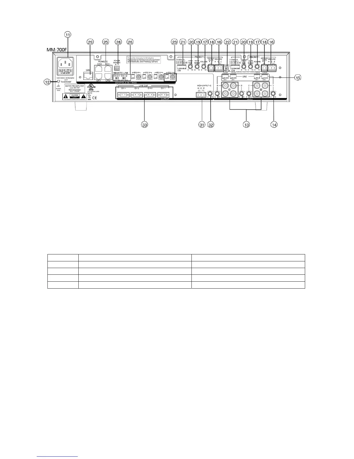
11. AC inlet
Connect the supplied power cord to this inlet. The socket-outlet should be installed near the equipment
and the plug (disconnected device) shall be easily accessible.
12. Functional ground terminal [SIGNAL GND]
Hum noise may be generated when external equipment is connected to the unit. Connecting this
terminal to the functional ground terminal of the external equipment may reduce the hum noise.
13. LINE 1, LINE 2, LINE 3, LINE 4 INPUT TERMINAL
10 kΩ,–10 dB*,unbalanced RCA Jack (Upper and lower of RCA input signal is mixed)
Connect music source equipment: e.g: CD players.
14. LINE 1, LINE 2, LINE 3, LINE 4 INPUT LEVEL CONTROL
Adjust the input level (sensitivity) of LINE 1, LINE 2, LINE 3, LINE 4.
15. ASSIGNMENT RESTRICTION DIP SWITCHES (LINE 1, LINE 2, LINE 3, LINE 4)
Assign restriction LINE 1, LINE 2, LINE 3, LINE 4 to CH1, CH2, CH3, CH4 outputs.
LINE 1 ASSIGNMENT RESTRICTIONS:
Switch No. ON OFF
1 LINE 1 can’t be assigned to CH1 LINE 1 can be assigned to CH1
2 LINE 1 can’t be assigned to CH2 LINE 1 can be assigned to CH2
3 LINE 1 can’t be assigned to CH3 LINE 1 can be assigned to CH3
4 LINE 1 can’t be assigned to CH4 LINE 1 can be assigned to CH4
Note: 1)
The functionality for LINE 2, LINE 3, LINE4 is the same as LINE 1.
2) When the assignment restriction is set, both INPUT SELECT SWITCH (10) or connected
WP-700, are not allowed to select the restricted channel.
16. MIC/LINE input terminal (PRIORITY 1, PRIORITY 2)
MIC: 2.2K, –60 dB*/ LINE: 2.2K, –10 dB*, electronically-balanced inputs of 3-pin removable terminal
block type.
Connect microphone or line level music source equipment. MIC/LINE gain could be from the PRIORITY
FUNCTIONAL DIP SWITCH (20) #6.
17. MIC/LINE input level control (PRIORITY 1, PRIORITY 2)
Adjust the input level (sensitivity) of the MIC/LINE
18. Manual mute terminal
Open voltage: DC 3.3V, Short current: <5mA
1) When (+), (-) shorted: The selected LINE 1, LINE 2, LINE3, LINE4 input signal to CH1, CH2, CH3,
CH4 output will be muted, and switch to the page channel (1st ~4th switch of (20)) that have been
assigned by PRIORITY 1, PRIORITY 2 inputs.
2) When (+), (-) opened:CH 1, CH 2, CH 3, CH 4 output will gradually recovered from the previous
assigned LINE 1, LINE 2, LINE3, LINE4 signal. The recovery time is controlled by the HOLD TIME
control (19).



 To Next Page