15
the filter setting is specified and no additional errors will occur.
[11]. Specifications are valid when sine wave input >1% range and >10μA AC. The 10A range is only available on
the front connector.
[12]. Specifications are applicable to the voltage measured at the input terminal. The 1 mA test current is typical
value. A change in the current source will cause a change in the voltage drop across the diode junction.
[13]. Unless otherwise stated, the specifications are valid when the instrument has warmed up for 60 minutes and
have a sine wave input. Specifications apply to 1s strobe time (7 digits). The signal is greater than 10% of the
selected range.
[14]. It is applicable when the sine and square wave are input larger than 100 mV. For a 10 mV to 100 mV input,
multiply the % of the reading error by 10.
[15]. The high-frequency signal has a serious attenuation in the latter stage, so the input voltage of the test signal
should be relatively larger. If the test signal is 1V-1MHz, the input signal is preferably greater than 50% of the
range.
[16]. The square wave input is specified as 10 Hz-300 kHz.
3.2 Supplementary specifications
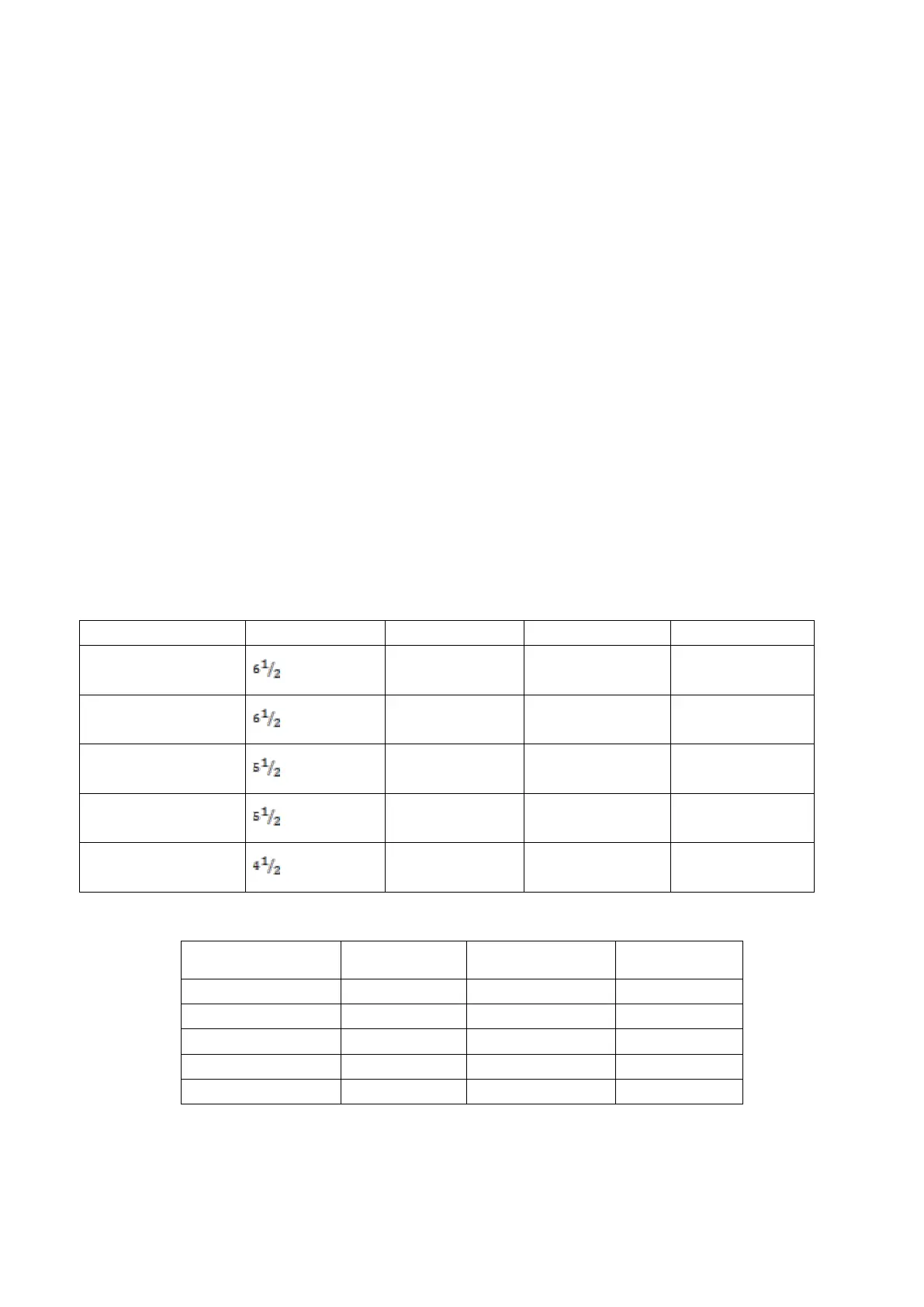
Display readings and measuring speed
DC resistance, DC voltage, DC current
[1]
AC voltage, AC current
[2] [3]
[1]. Reading rate at 60-Hz and 50-Hz operating conditions, turning off auto zero, within a fixed range.
[2]. The number of display digits in the case of automatically displaying the number of digits. If a fixed number of