38
8. Therefore, the voltage signal cannot be used as a strong drive signal. If a strong drive capability is required,
an external power supply is recommended.
9. EOC indicates the end of the test, and the output signal only makes sense after the test is over.
10. START is trigger signal. There is need to set the trigger condition before triggering.
11. PASS, FALL output signal can be adjusted, that is, select high level output, low level output, high pulse
output or low pulse output. This adjustable state is sufficient to meet the different needs of customers.
6.2.1 Handler setup
Step 1: Set the instrument trigger mode.
The trigger mode is set to external trigger and at this time you can use the Handler to trigger.
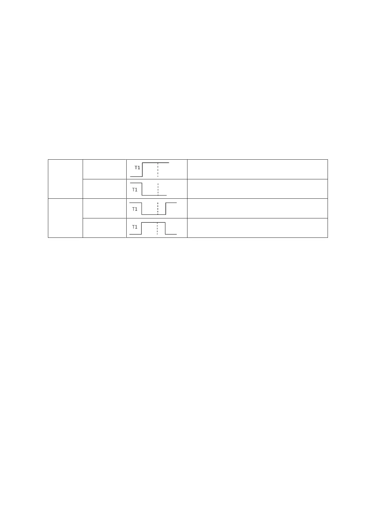
Step 2: Set the trigger mode of the external trigger
T1 trigger time, after the rising edge, keep the high
level is greater than the trigger time to trigger
T1 trigger time, after the falling edge, keep the
high level is greater than the trigger time to trigger
T1 trigger time, the pulse width must be greater
than the width of T1 to trigger the test
T1 trigger time, the pulse width must be greater
than the width of T1 to trigger the test
The difference between edge trigger and pulse width trigger: edge trigger only needs the corresponding edge, and
then delay a period of time longer than the set delay time to trigger the measurement. The pulse width trigger
requires a delay of time longer than the set delay time after the first edge, and then an opposite edge signal to
trigger the test.
Step 3: trigger time
The trigger time here is the trigger time that needs to be maintained at high and low levels. Only when such
trigger time is met will the test be triggered. The default trigger time is 10uS. This has the advantage of
eliminating some noise interference.
Step 4: Set the output logic of PASS and FALL
First, make sure that PASS is valid at IN, or valid at LO or HI. The default is IN.
Second, determine the state in effective time is to keep high or low level, or high and low pulses. The default is
active high.
Note: The output status of PASS0, FALL0, IN0, LO0, HI0, PASS1, FALL1, IN1, LO1, HI1 is not settable, and the
default high level is valid.
Step 5: EOC Trigger Logic
If the EOC is active low, it changes to high level after the test starts and changes to low level when the test ends.
If the EOC is active high, it changes to low level after the test starts and changes to high level when the test ends.
Step 6: Open the Handler interface