21
Step 4: AC Filter Selection.
The instrument offers three filter options of 3Hz, 20Hz and 200Hz. The filter you choose should be less than the
frequency of your test signal. In order to get stable data faster, the filter is best chosen to be close to the test
frequency of your input signal. For example, if the input signal is 300Hz, the stable data can be obtained as soon
as the filter selects 200Hz.
Step 5: Speed selection.
Different filters have different test speeds, so choosing the right measurement speed based on the filter can result
in more accurate test results or faster test speeds.
4.2.4 DC Current
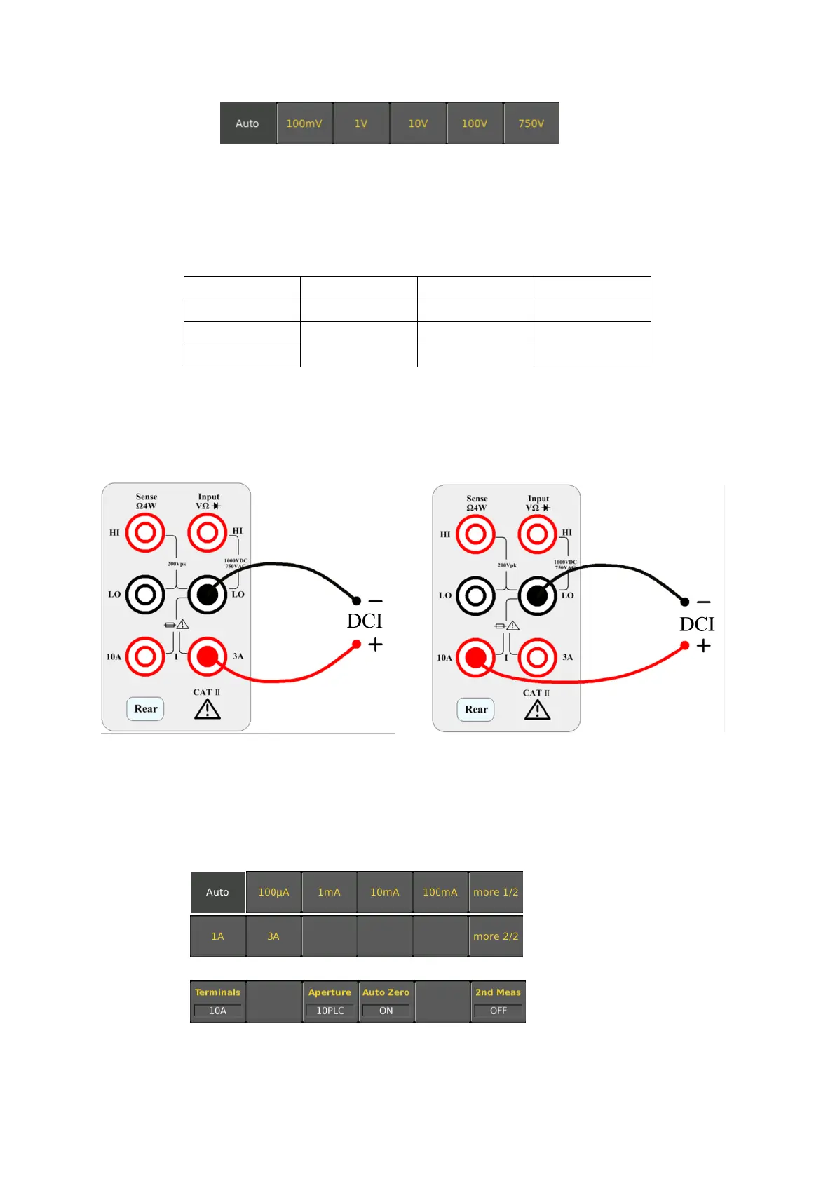
Step 1: Configure the test leads as follows:
Step 2: Press the shift button on the front panel and press [DCV] to select the DCI function and enter the DCI
measurement interface.
Step 3: Select the range.
Select the input terminal for the test signal. If you select 10A input terminal, there is only 10A range. If you select
3A input terminal, there are multiple ranges. At this time, you can select auto range test.
The range that can be selected by selecting the 3A input terminal is as follows:
The range that can be selected by selecting the 10A input terminal is as follows:
If selecting the 3A terminal, there are multiple ranges to choose from at this time. You can select 100uA, 1mA,
10mA, 100mA, 1A, 3A or auto range as needed.