37
6.2 Handler Interface
Many instruments are used in industrial control. In order to better use with control signals, the Handler interface is
added to facilitate the use of the instrument on the production line.
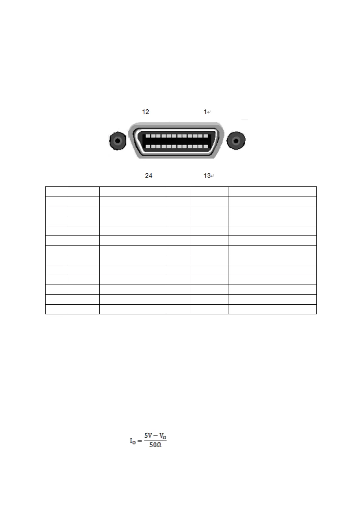
Because the space is limited, the interface used is the same as the GPIB interface, and the interface terminals used
are the same.
Front panel indicator signal
Test result is just right
Rear panel indicator signal
Test result is just right
1. When the Limit function is ON, the trigger of the Handler interface works.
2. IN indicates that the test result is between the upper and lower limits of the setting; LO indicates that the test
result is less than the lower limit; HI indicates that the test result is greater than upper limit.
3. PASS0, FALL0, IN0, LO0, and HI0 indicate the test results of the front panel. PASS1, FALL1, IN1, LO1,
and HI1 indicate the test results of the rear panel. When the front panel is selected, the logo on the rear panel
has no meaning. When the rear panel is selected, the label on the front panel has no meaning.
4. Front indicates that the test is currently on the front panel
5. Rear indicates that the test is currently performed on the rear panel.
6. EXT_VCC and EXT_GND are the high and low terminals of the external power supply.
7. VDD is the internal supply voltage, about 5V, but the drive capability is not strong. The relationship between
the output current I
O
and the output voltage V
O
is approximately: