10
current, the signal-to-noise ratio will be small and the test will be unstable.
[8]. Specifications are applicable to 4-wire or 2-wire resistance measurements. When the zero clearing is not
activated, the 2-wire resistance measurement will increase the additional error of 0.2Ω.
[9]. Specifications are valid when the sine wave input is >0.3% of the range and greater than 1mVrms. The
750-ACV range is limited to the 8 x Volt–Hz range.
[10]. Low Frequency Performance: three filter settings are available: 3 Hz, 20 Hz, 200 Hz. The frequency above
the filter setting is specified and no additional errors will occur.
[11]. Specifications are valid when sine wave input >1% range and >10μA AC. The 10A range is only available on
the front connector.
[12]. Specifications are applicable to the voltage measured at the input terminal. The 1 mA test current is typical
value. A change in the current source will cause a change in the voltage drop across the diode junction.
[13]. Unless otherwise stated, the specifications are valid when the instrument has warmed up for 60 minutes and
have a sine wave input. Specifications apply to 1s strobe time (7 digits). The signal is greater than 10% of the
selected range.
[14]. It is applicable when the sine and square wave are input larger than 100 mV. For a 10 mV to 100 mV input,
multiply the % of the reading error by 10.
[15]. The high-frequency signal has a serious attenuation in the latter stage, so the input voltage of the test signal
should be relatively large. The test signal is 1V-1MHz, and the input signal is preferably greater than 50% of the
range.
[16]. The square wave input is specified as 10 Hz-300 kHz.
2.2 Supplementary specifications
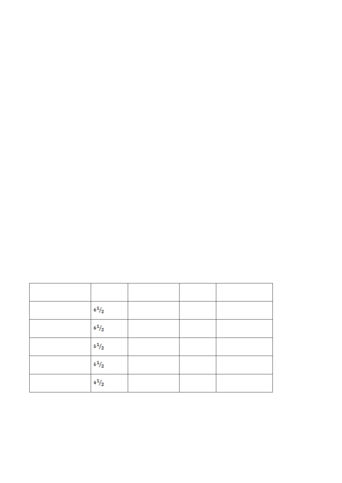
Display readings and measuring speed
DC resistance, DC voltage, DC current
[1]