2 PREPARING FOR USE
2-14
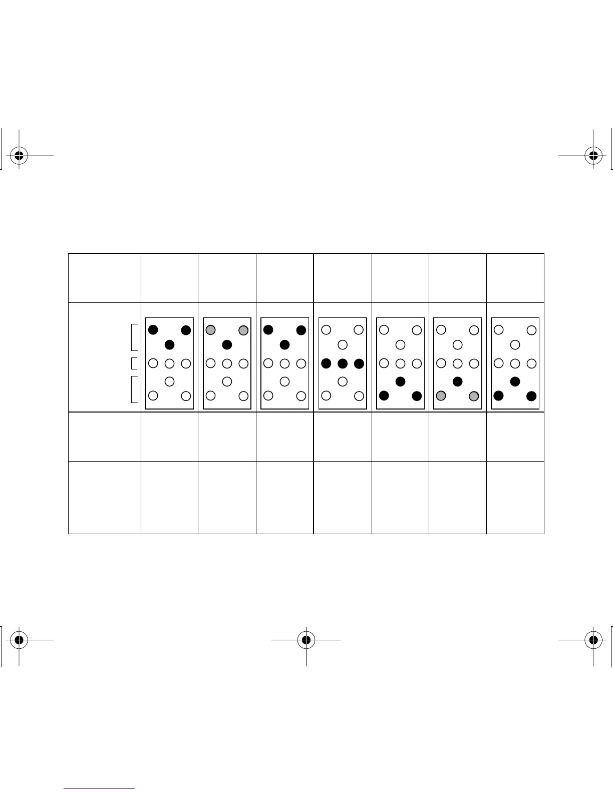
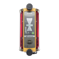
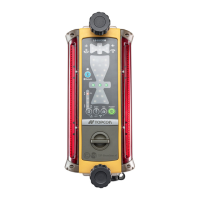
This illustration depicts the reaction of LS-B4 display as the sensor is moved down
through the path of a rotating laser.*
* This illustration is for reference only. Actual blade direction adjustment could vary based on the motion and atti-
tude of machine.
** Tolerance may vary based on rotating laser used, distance from laser instrument or atmospheric conditions.
Blade
direction to
achieve
on-grade*
DOWN DOWN DOWN
ON-
GRADE UP UP UP
LED display
indication
Blinks
slowly
(yellow)
Blinks
quickly in
sequence
(yellow)
Blinks
quickly
(yellow)
Blinks
quickly
(green)
Blinks
quickly
(red)
Blinks
quickly in
sequence
(red)
Blinks
slowly
(red)
Blade position
relative to
on-grade
Very High
Sensor is
above laser
beam*
High Slightly
High
On-grade**
to within:
±6mm
(Mode 1)
±20mm
(Mode 2)
Slightly
Low
Low Very Low
Sensor is
below laser
beam*
Yellow
Green
Red
LED Color
LS-B4E-1.book14 ページ 2001年5月18日 金曜日 午前11時59分