8 Instructions for Use T-1929 e
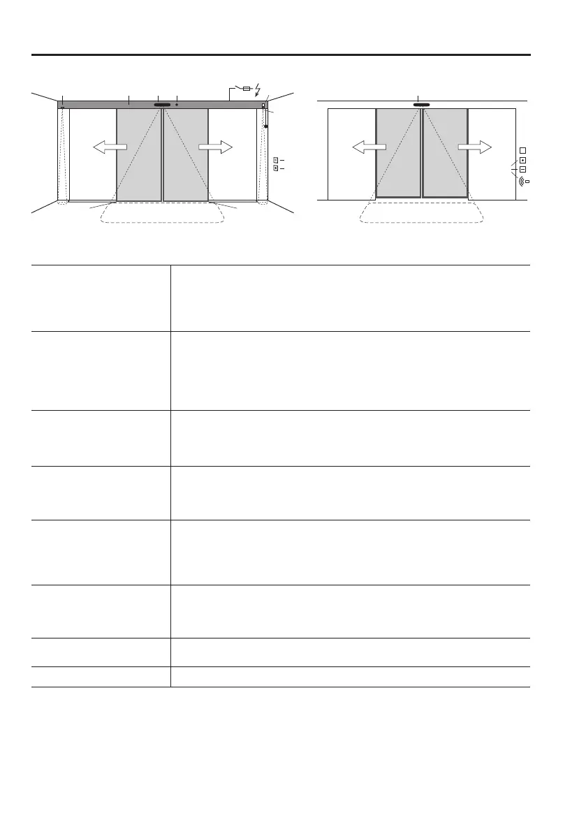
3 System Overview
1 Drive
Cladding
Motor unit
MCU42 control system with monitoring system, power limitation and
permanent diagnosis
Guide system with noise-absorbent guide rail
2 Drive accessories
a) £ Mains switch *
b) £ Lock with:
c) £ internal manual activation £ in the cladding £ on the wall
d) £ external manual activation
£ Emergency power supply via the battery unit
£ Mechanical emergency opening
3 Door leaves
a) Moving leaves with main closing edge (HK) and secondary closing edge (NK)
b) Floor guide for moving leaves *
c) £ Side part *
d) £ Protection leaves as protection for the secondary closing edge *
4 Operating controls
a) £ User interface USIN-7 with 6 operating modes and fault display
b) £ Operating mode switch with 3 positions.
c) £ Lock for the user interface
£ Remote control of operating modes
5 Activators drive side
a) with automatic activation b) with manual activation
£ Combined sensor (activator/safety HK) £ Push button *
£ Radar with/without direction recognition * £ Contact-free button *
£ IR motion detector *
c) £ Presence sensor *: Securing the secondary closing edge (NK)
6 Activators opposite
drive side
a) with automatic activation b) with manual activation
£ Combined sensor (activator/safety) £ Key switch
£ Radar with/without direction recognition * £ Card reader *
£ IR motion detector * £ Remote control *
7 Output message
£ Bell / gong * £ Light / ventilation * £ Door status message 1
£ Door status message 2
8 Low-energy
£ Yes £ No
£ Depending on the system’s equipment
* Not oered by the manufacturer.
The company installing the system must select and install suitable components in accordance with the
product standard EN16005.
T1929_2e
3c 3a 3a
HK
Drive side Opposite drive side
NK NK
5a
3d
3c
3d
3b 3b
1
4a
4c
6a
6b
2b 4b5c
5c
2c
2a
2d