46
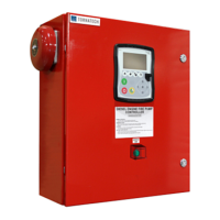
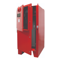
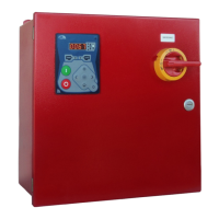
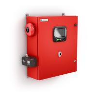
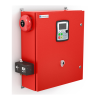
TORNATECH MODEL HFD DIESEL FIRE PUMP CONTROLLER
PRE- FIELD ACCEPTANCE TEST
CHECK LIST
Note: This document should be an official indication of whether or not the installation and general condition
of the equipment is adequate for a field acceptance test. This document should also aid the individual
responsible for executing the field acceptance test to decide whether or not to carry out the field acceptance
test of the equipment.
Verify that the nameplate voltages of the Fire Pump Controller corresponds with the AC
voltage available and the DC starting voltage of the engine.
Visual inspection for any damage to the exterior of the Fire Pump Controller. Make sure
the enclosure, alarm bell, selector switch, membrane and display are not damaged.
Verify that the Fire Pump Controller has been installed within sight of the pump and engine
or motor.
Verify that the Fire Pump Controller has been installed not less than 12 inches from the
floor of the mechanical room.
Verify that all electrical connections to the Fire Pump Controller are done using liquid tight
conduit and connectors.
With the Fire Pump Controller door open, visually inspect for any drill chips, dirt or foreign
objects in the bottom of the enclosure, loose wires, broken components and general
proper electrician workmanship.
Verify that the correct AC voltage is supplied to the controller by taking a voltage reading at
the L & N (220-240) terminals.
Verify that the terminal connections between the Fire Pump Controller and the engine (1 to
11 and 12 for Caterpillar engines) are properly done.
Verify that wiring to terminals #6, #8 (batteries) and #11 (ground) are of the appropriate
gauge size. See label inside controller.
Verify proper grounding of the Fire Pump Controller.
Initial Power-Up Check List:
With the Fire Pump Controller door open, turn to “ON” the circuit breakers CB3 and CB4
(DC) then CB1 and CB2 (AC), then IS1. This sequence is very important.
Close the Fire Pump Controller door. Verify on the ViZiTouch Homepage that the correct
battery voltage appears.
Manual and Automatic Start Check List:
Verify starting of engine by pressing the “Start” membrane button.
Stop engine by pressing the “Stop” membrane button.
Verify the starting of engine by pressing the emergency push button.
Stop engine by pressing the “Stop” membrane button.