36
Config > Advanced > Debug > IO
The small white circle beside each signal is a representation of its state. If the white circle is filled with a green dot,
then the signal is activated. Comparing these software signals and the physical state of the signal on the electronic
board is the best way to troubleshoot. In the right column, additional “TEST” buttons are located beside each output
signal. Clicking on these buttons will toggle the output state of this signal, again allowing a comparison between the
software and hardware state of these signals to help troubleshoot.
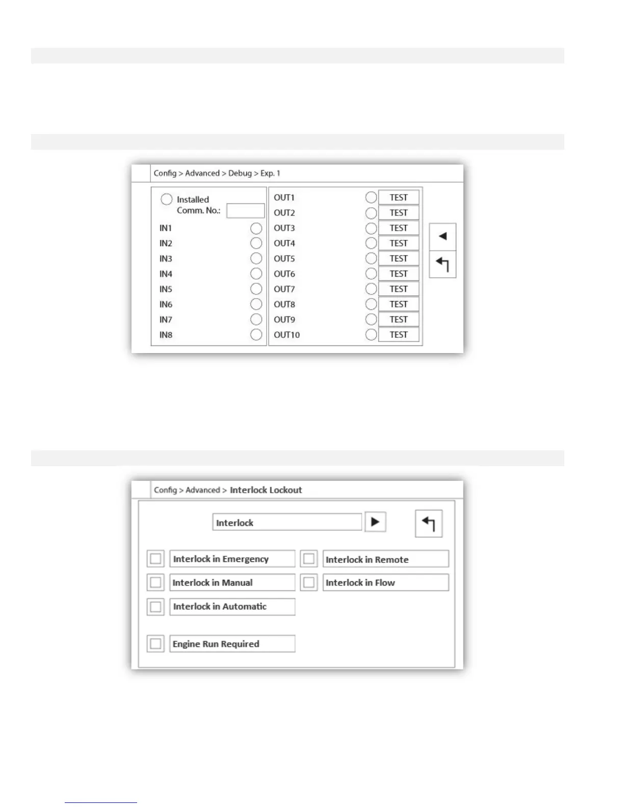
Config > Advanced > Debug > Expansion
The small white circle beside each signal is a representation of its state. If the white circle is filled with a green dot,
then the signal is activated. The first element in the left column is the indication of whether or not the optional
Expansion board is installed. In the box, the corresponding Expansion board number is displayed. Comparing
between these software signals and the physical state of the signal on the electronic board is the best way to
troubleshoot. In the right column, additional “TEST” buttons are located beside each output signal. Clicking on these
buttons will toggle the output state of this signal, again allowing a comparison between the software and hardware
state of these signals to help troubleshoot.
Config > Advanced > Interlock Lockout