Important Notice!
Every analog sensor cable used for this controller should be shielded. The shield has to be grounded on the motor
side. Not complying to these recommendations may affect the controller good functioning and void its warranty.
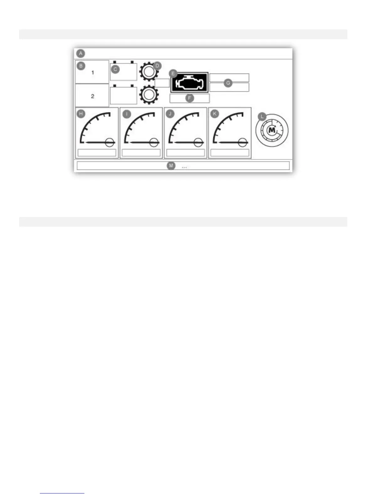
The tachometer (analog speed reading) gives the possibility to support engine with no electronic speed switch. The
magnetic pickup must be connected to the MP+MP- inputs on the I/O Board.
The first small green line and small red line on the gradations shows the Set point of the “Engine Run” Signal. When
the engine runs with a speed above this threshold, the ViZiTouch will consider it is running, and when it slows down
under the red line, it will be considered stopped. The second red line, usually set high on the gauge, represents the
“Overspeed” threshold. If the engine reaches that speed, the “Overspeed” alarm will be activated.
The rectangle box below the gauge is the odometer, showing the run time of the engine since the first startup.
Pressing on the gauge will bring the user to the “Config > Advanced > Engine Speed” page.