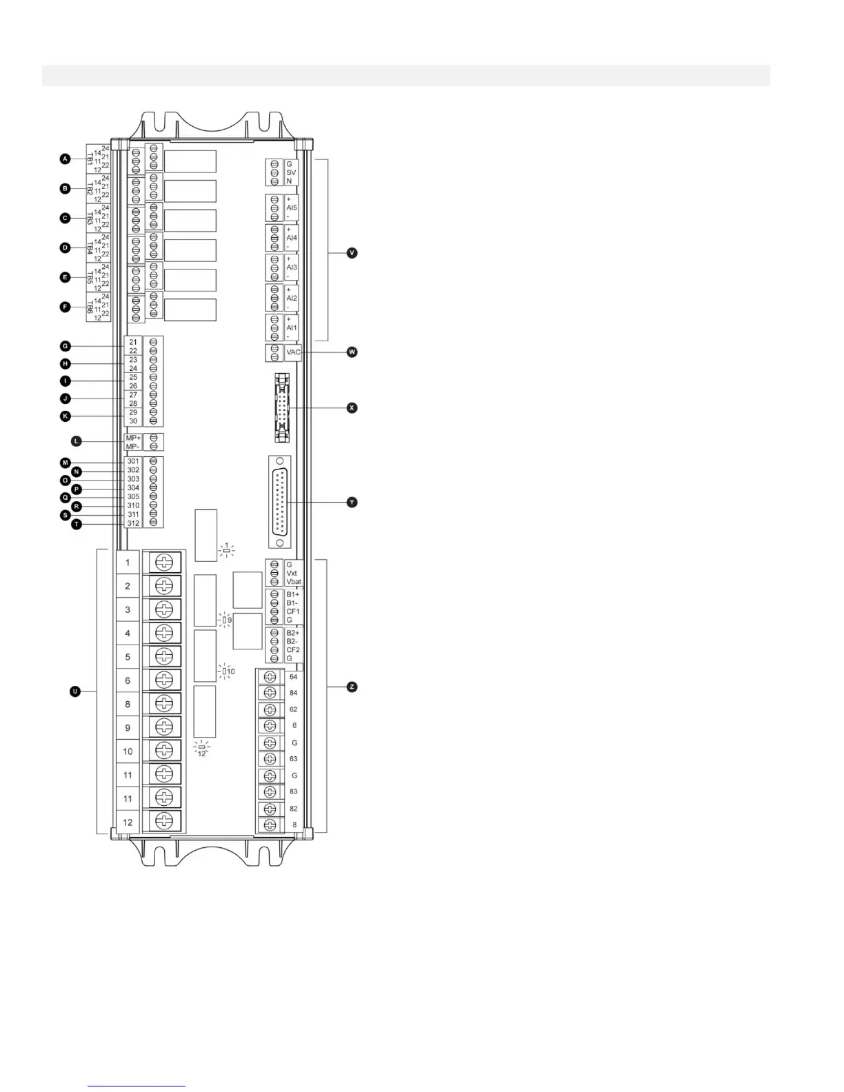
A-F : Alarm Output Terminals
(DPDT Relay, 11/21:Common, 12/22:Normally Closed,
14/24:Normally Open):
A: Controller Trouble (Fail safe)
B: Engine Run
C: Automatic Mode Bypass (Fail safe)
D: Fail to Start
E: Engine Trouble
F: Pump Room Alarm
G-T : Field Input Terminal
(Dry Contact Only: Voltage Free):
G: Emergency Button
H: Remote Automatic Start (NC)
I: Deluge Valve (NC)
J: Fuel Tank Leak (NO)
K: Low Fuel Level (NO)
L: Engine RPM Magnetic Pickup
M: Not Used
N: Not Used
O: Not Used
P: Not Used
Q: Not Used
R: Not Used
S: Not Used
T: Not Used
U : Engine Terminals :
The terminals are numbered according to the standard:
1 - FS : fuel solenoid valve (energized to start)
2 - Not used
3 - Not used
4 - Not used
5 - Not used
6 - B1 : battery #1 positive
8 - B2 : battery #2 positive
9 - C1 : start contactor #1
10 - C2 : start contactor #2
11 - GND : Ground
12 - ST : stop fuel solenoid valve
(ETS - energized to stop)
V: Analog inputs
SOL V: Not Used
AI1: Not Used
AI2: Not Used
AI3: Oil Pressure transducer
AI4: Fuel Level analog input
AI5: Engine Temperature transducer
W: AC Voltage reading
X: CANBUS to IO cards
Y: CANBUS to ViZiTouch
Z: Factory reserved power connections