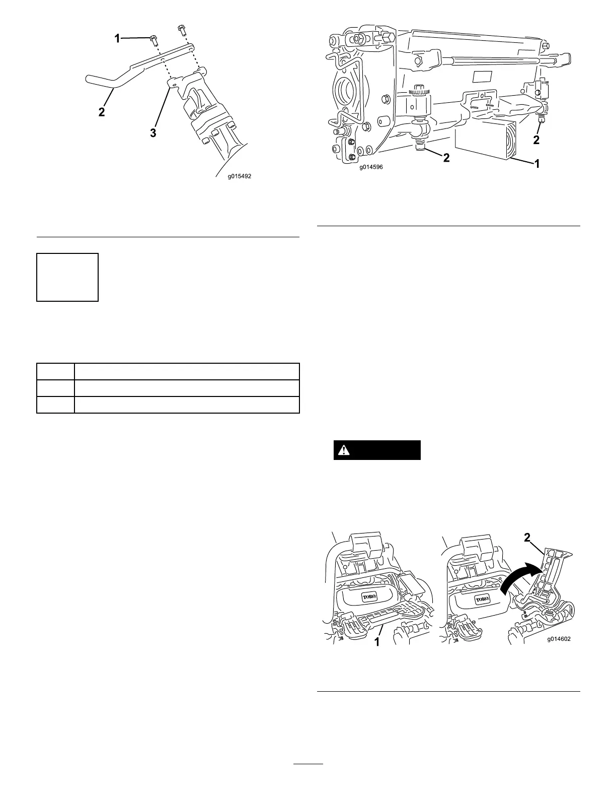
Figure8
1.Flangebolt
3.Suspensionarmbar
2.Grassbaskethook
7
InstallingtheCuttingUnits
Partsneededforthisprocedure:
1
Gaugebar
3
Cuttingunit(model04613,04614,or04615)
3
GrassBasket
Procedure
Note:Whensharpening,settingtheheight-of-cut,
orperformingothermaintenanceproceduresonthe
cuttingunits,storethecuttingunitreelmotorsinthe
storagelocationonthefrontofthesuspensionarmsto
preventdamagetothem.
Important:Donotraisethesuspensiontothe
transportpositionwhenthereelmotorsareinthe
holdersinthemachineframe.Damagetothe
motorsorhosescouldresult.
Important:Wheneverthecuttingunithastobe
tippedtoexposebedknife/reel,propuprearof
cuttingunittomakesurenutsonbackendof
bedbaradjustingscrewsarenotrestingonwork
surface(
Figure9).
Figure9
1.Prop(notprovided)2.Bedknifeadjustingscrew
nut(2)
Note:Allcuttingunitsareshippedwiththecounter
weightmountedtotherightendandthemotormount
anddrivecouplermountedtotheleftendofthecutting
unit.
1.Applygreasetotheinsidediameterofthedrive
coupler.
2.Thecuttingunitisshippedwithoutafrontroller.
Obtainaroller(ModelNo.04625,04626or04627)
fromyourlocalToroDistributor.Installtheroller
usingtheloosepartssuppliedwiththecuttingunit
andinstallationinstructionsincludedwiththeroller.
3.Ifinstallingthecentercuttingunit,liftuponthefoot
restandswingitup,allowingaccesstothecenter
cuttingunitposition(
Figure10).
CAUTION
Thefootrestcanpinchngersifitfallsintothe
closedposition.
Keepyourngersclearoftheareawherethe
footrestseatswhileitisopen.
Figure10
1.Footrest—closed2.Footrest—open
4.Positionthecuttingunitunderthesuspensionarm.
5.Withthelatchesonthesuspension-armbarpointing
up(i.e.,open)(Figure11),pushthesuspensionarm
17