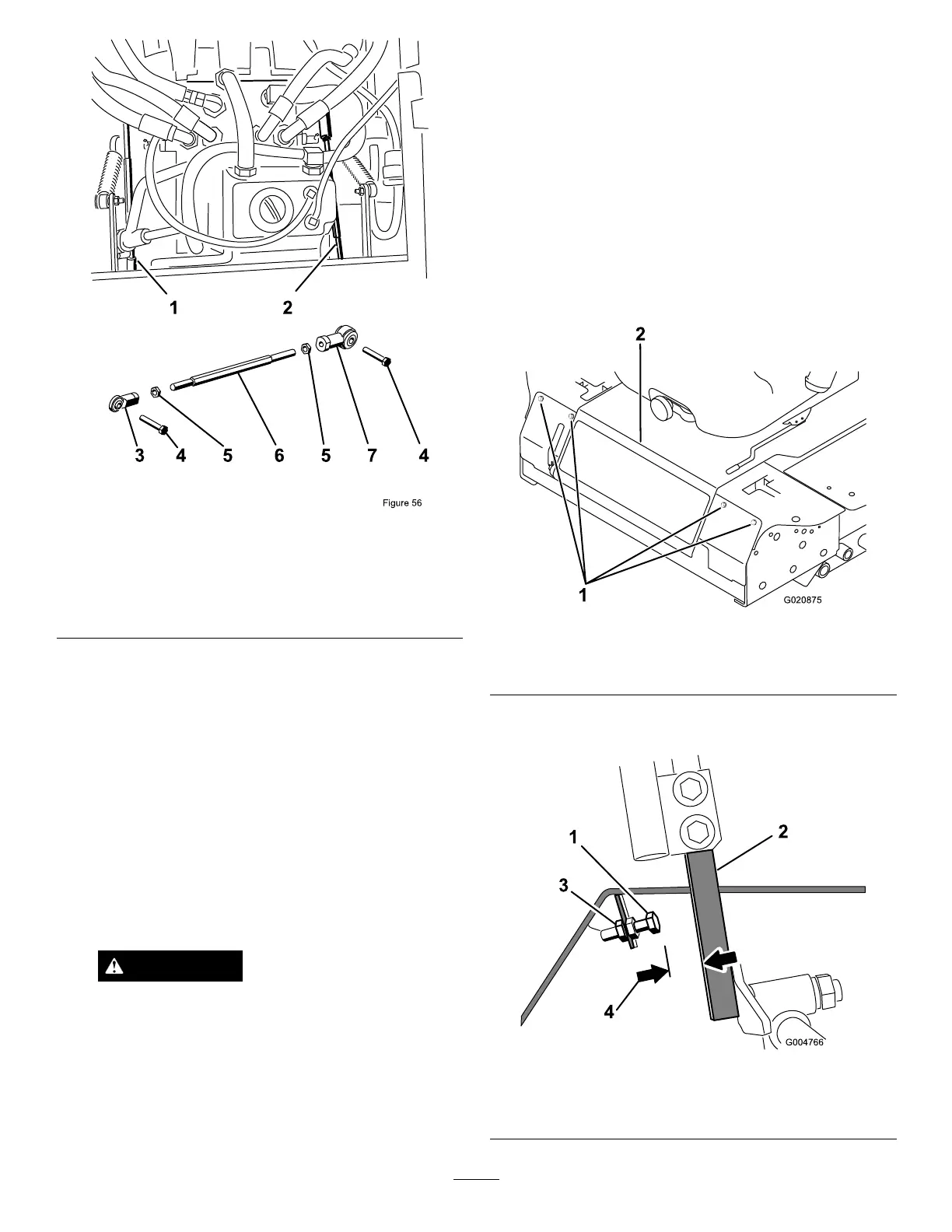
Figure84
1.Rightpumprod5.JamNut
2.Leftpumprod6.Hexshaft
3.Balljoint7.Balljoint
4.Bolt
7.Movethemotioncontrolleverforwardandreverse,
thenbacktoneutral.Thewheelmuststopturningor
slightlycreepinreverse.
8.MovethethrottlelevertotheFastposition.Makesure
thatthewheelremainsstoppedorslightlycreepsin
reverse;adjustitifnecessary.
9.Repeatsteps6through8fortheothersideofthe
machine.
10.Tightenthejamnutsattheballjoints(
Figure82).
11.MovethethrottlelevertotheSlowpositionandstop
theengine.
12.Removethejumperwirefromthewireharness
connectorandplugtheconnectorintotheseatswitch.
WARNING
Electricalsystemwillnotperformproper
safetyshutoffwithjumperwireinstalled.
•Removejumperwirefromwireharness
connectorandplugconnectorintoseat
switchwhenadjustmentiscompleted.
•Neveroperatethisunitwithjumper
installedandseatswitchbypassed.
13.Lowertheseatintoposition.
14.Removethejackstands.
AdjustingtheMaximum
GroundSpeed
1.DisengagethePTO,movethemotioncontrolleversto
theneutrallockedposition,andsettheparkingbrake.
2.MovethethrottlelevertotheSlowposition,stopthe
engine,removethekey,andwaitforallmovingpartsto
stopbeforeleavingtheoperatingposition.
3.Removetheboltssecuringthefrontpanelandremove
thepanel(
Figure85).
Figure85
1.Bolts
2.Controlpanel
4.Loosenthejamnutonthestopboltforoneofthe
controllevers(Figure86).
Figure86
1.Stopbolt
3.Jamnut
2.Controllever4.0.060inch(1.5mm)
59