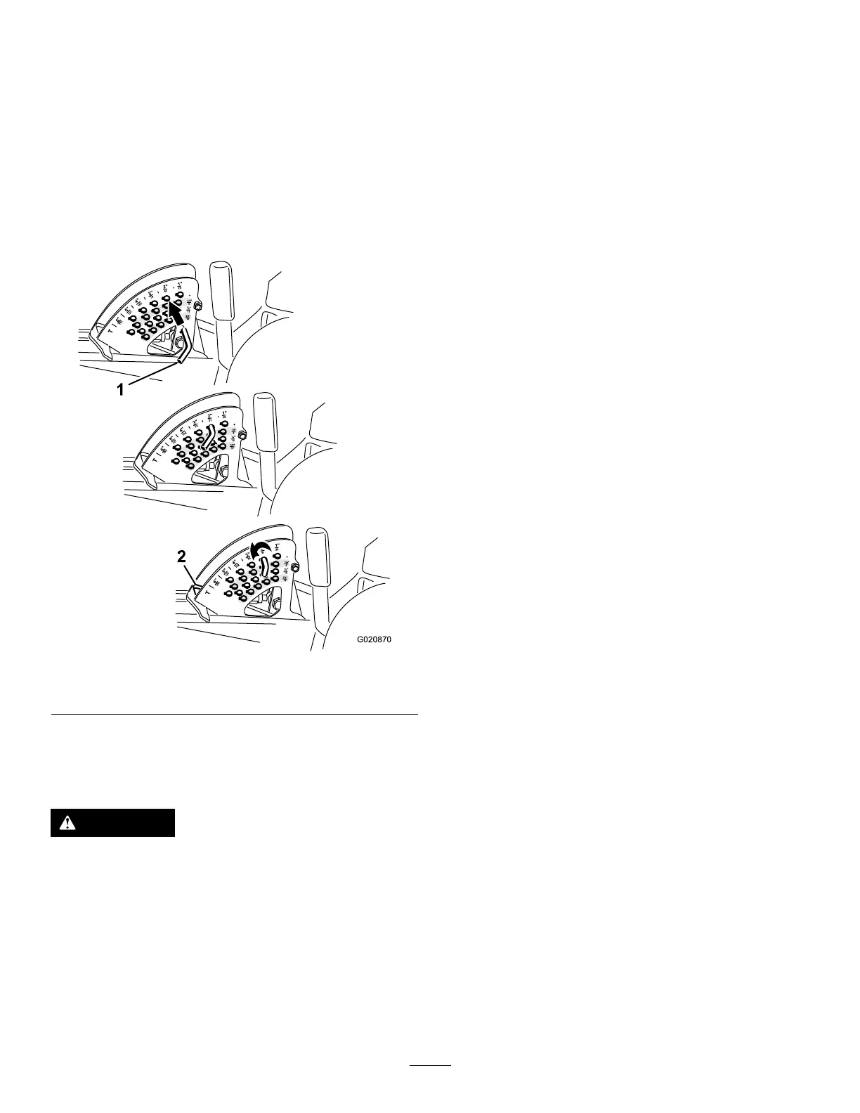
3.Selectaholeintheheight-of-cutbracketcorresponding
totheheight-of-cutdesired,insertthepin,androtateit
downtolockitinplace(Figure19).
Note:Thereare4rowsofholepositions(Figure19).
Thetoprowgivesyoutheheightofcutlistedabovethe
pin.Thesecondrowdowngivesyoutheheightlisted
plus6mm(1/4inch).Thethirdrowdowngivesyou
theheightlistedplus12mm(1/2inch).Thebottom
rowgivesyoutheheightlistedplus18mm(3/4inch).
Forthe15.8cm(6inch)positionthereisonlyonehole,
locatedinthesecondrow .Thisdoesnotadd6mm
(1/4inch)tothe15.8cm(6inch)position.
Figure19
1.Stoppin2.Height-of-cutstop
4.Adjusttheanti-scalprollersandskidsasrequired.
TheSafetyInterlockSystem
CAUTION
Ifthesafetyinterlockswitchesaredisconnectedor
damagedthemachinecouldoperateunexpectedly
causingpersonalinjury.
•Donottamperwiththeinterlockswitches.
•Checktheoperationoftheinterlockswitches
dailyandreplaceanydamagedswitchesbefore
operatingthemachine.
UnderstandingtheSafetyInterlock
System
Thesafetyinterlocksystemisdesignedtopreventtheengine
fromstartingunless:
•Youaresittingontheseatortheparkingbrakeisengaged.
•Thepowertake-off(PTO)isdisengaged.
•Themotion-controlleversareintheneutrallocked
position
•Theenginetemperatureisbelowthemaximumoperating
temperature.
Thesafetyinterlocksystemalsoisdesignedtostoptheengine
whenthetractioncontrolsaremovedfromtheneutrallocked
positionwiththeparkingbrakeengaged.Ifyourisefromthe
seatwhenthePTOisengagedthereisa1-seconddelayand
thentheenginestops.
23