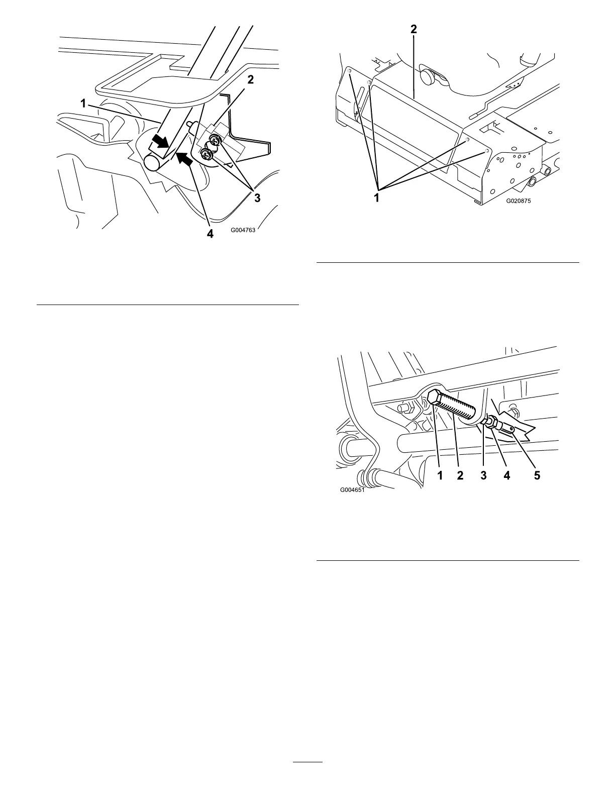
Figure45
1.Controllever3.Screws
2.Neutralinterlockswitch
4.0.4to1mm(0.015to
0.045inch)
4.Holdingthecontrolleveragainsttheframe,movethe
switchtowardtheleveruntilthedistancebetweenlever
andswitchbodyis0.4to1mm(0.015to0.045inch)
(Figure45).
5.Securetheswitch.
6.Repeatsteps3to5fortheotherlever.
7.Installthefrontpanel.
AdjustingtheControlLever
NeutralReturn
Ifthemotioncontrolleversdonotalignwiththeneutralslots
whenreleasedfromthereversedriveposition,adjustmentis
required.Adjusteachlever,spring,androdseparately.
1.DisengagethePTO,movethecontrollevertothe
neutrallockedposition,andsettheparkingbrake.
2.MovethethrottlelevertotheSlowposition,stopthe
engine,removethekey,andwaitforallmovingpartsto
stopbeforeleavingtheoperatingposition.
3.Removetheboltssecuringthefrontpanelandremove
thepanel(Figure46).
Figure46
1.Bolts
2.Controlpanel
4.Movethecontrollevertotheneutralpositionbutnot
locked(Figure48).
5.Pulltheleverbackuntiltheclevispin(onanarm
abovethepivotshaft)contactstheendoftheslot(just
beginningtoputpressureonthespring)(Figure47).
Figure47
1.Clevispin
4.Adjustmentbolt
2.Slot
5.Yoke
3.Jamnuts
6.Checkwherethecontrolleverisrelativetonotchin
console(Figure48).
Note:Itshouldbecenteredallowinglevertopivot
outwardtotheneutrallockposition.
43