BladeMaintenance
BladeSafety
Awornordamagedbladecanbreak,andapiece
ofthebladecouldbethrownatyouorbystanders,
resultinginseriouspersonalinjuryordeath.
•Inspectthebladeperiodicallyforwearordamage.
•Usecarewhencheckingtheblades.Wrapthe
bladesorweargloves,andusecautionwhen
servicingtheblades.Onlyreplaceorsharpenthe
blades;neverstraightenorweldthem.
•Onmulti-bladedmachines,takecareasrotating1
bladecancauseotherbladestorotate.
ServicingtheBladePlane
Thecuttingunitcomesfromthefactorypresetat5
cm(2inches)heightofcutandbladerakeof7.9mm
(0.310inch).Theleftandrightheightsarealsopreset
towithin±0.7mm(0.030inch)oftheother.
Thecuttingunitisdesignedtowithstandblade
impactswithoutdeformationofthechamber.Ifthe
bladestrikesasolidobject,inspectthebladefor
damageandthebladeplaneforaccuracy.
InspectingtheBladePlane
1.Removethehydraulicmotorfromthecuttingunit
andremovethecuttingunitfromthemachine.
2.Useahoist(orminimumof2people)andplace
thecuttingunitonaattable.
3.Mark1endofthebladewithapaintpenor
marker.Usethisendofthebladetocheckall
heights.
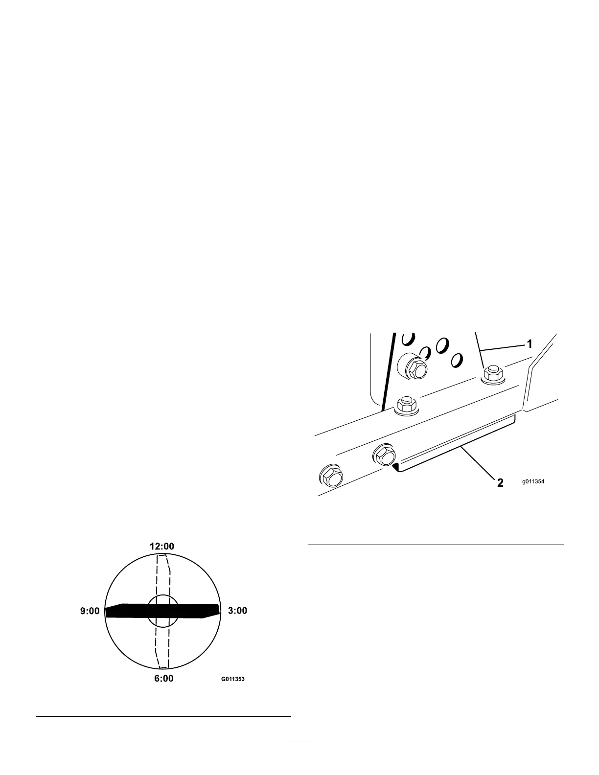
4.Positionthecuttingedgeofthemarkedendof
thebladeat12o’clock(straightaheadinthe
directionofmowing)(Figure122)andmeasure
heightfromtabletocuttingedgeofblade.
g011353
Figure122
5.Rotatethemarkedendofthebladetothe3and
9o’clockpositions(Figure122)andmeasure
theheights.
6.Comparethe12o’clockmeasuredheighttothe
height-of-cutsetting.Itshouldbewithin0.7mm
(0.030inch).The3and9o’clockheightsshould
be1.6to6.0mm(0.060to0.240inch)higher
thanthe12o’clocksettingandwithin2.2mm
(0.090inch)ofeachother.
Ifanyofthesemeasurementsarenotwithin
specication,proceedtoAdjustingtheBladePlane
(page78).
AdjustingtheBladePlane
Startwiththefrontadjustment(change1bracketata
time).
1.Removetheheight-of-cutbracket,(front,left,or
right)fromthecutting-unitframe(Figure123).
2.Adjust1.5mm(0.060inch)shimsand/or0.7
mm(0.030inch)shimsbetweenthecutting-unit
frameandbrackettoachievethedesiredheight
setting(Figure123).
g011354
Figure123
1.Height-of-cutbracket2.Shims
3.Installtheheight-of-cutbrackettothecutting-unit
framewiththeremainingshimsassembled
belowtheheight-of-cutbracket.
4.Securethesocket-headbolt/spacerandange
nut.
Note:Socket-headbolt/spacerareheld
togetherwiththread-lockingadhesivetoprevent
thespacerfromfallinginsidethecutting-unit
frame.
5.Verifythe12o’clockheightandadjustifneeded.
6.Determineifonly1orboth(rightandleft)
height-of-cutbracketsneedtobeadjusted.
78