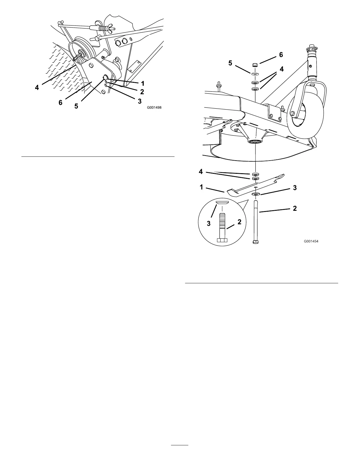
Figure9
1.PositionA4.Drivespring
2.PositionB
5.Adjustmentbolt(In
positionA)
3.PositionC
6.Drivepulleyshield
5.Removethelocknutthatsecurestheadjustment
bolttothedrivepulleyshield(Figure9).
6.Locateboltassemblyinthedesiredtensionposition
asfollows:
•PositionAfornormalconditions
•PositionBformoresevereconditions
•PositionCforthemostsevereconditions
Note:Thewheeldrivetensionislowestwhen
theboltassemblyisinPositionA.Thetension
increasesinPositionsBandC(Figure9).
7.Installtheadjustmentboltandthedrivespring.
8.Repeatstepsthroughfortheoppositeside.
AdjustingtheHeight-of-Cut
Thismachinehasa1to4-1/4inch(26to108mm)
rangefortheheight-of-cut.Thiscanbeachievedby
adjustingbladespacers,rearaxleheight,andfront
casterspacers.UsetheHeight-of-CutCharttoselect
thecombinationofadjustmentsrequired.
AdjustingtheBladeHeight
Adjustthebladesbyusingthe4spacers(1/4inch)
(6mm)onthebladespindlebolts.Thisallowsfora
1-inch(25mm)adjustmentrange,in1/4inch(6mm)
increments,ofcuttingheightinanyaxleposition.Use
thesamenumberofbladespacersonallbladesto
achievealevelcut(2aboveand2below,1aboveand3
below,etc.).
1.Disengagethebladecontrol(PTO)leverandset
theparkingbrakes.
2.Stoptheengineandwaitforallmovingpartsto
stopbeforeleavingtheoperatingposition.
3.Holdthebladeboltandremovethenut(Figure10).
Figure10
1.Blade
4.Spacer
2.Bladebolt5.Thinwasher
3.Curvedwasher
6.Nut
4.Slidetheboltdownthroughthespindle,andchange
thespacersasneeded(Figure10).
5.Installtheboltandcurvedwasher,addextra
spacer(s),andsecurethemwithathinwasheranda
nut(Figure10).
6.Torquethebladeboltto75-80ft-lb(101-108N⋅m).
AdjustingtheAxleHeight
Adjusttheaxlepositiontotheselectedheight-of-cut
setting.RefertotheHeight-of-CutChart.
1.Disengagethebladecontrol(PTO)leverandset
theparkingbrakes.
2.Stoptheengineandwaitforallmovingpartsto
stopbeforeleavingtheoperatingposition.
3.Loosen,butdonotremove,the2axlepivotbolts
andthe2axleadjustmentbolts(Figure11).
16