1.Disengagethebladecontrol(PTO)leverandsetthe
parkingbrakes.
2.Stoptheengineandwaitforallmovingpartstostop
beforeleavingtheoperatingposition.
3.Loosenthelocknutontheturnbuckle(Figure34).
4.Rotatetheturnbuckletowardtherearofthe
mowertoincreasethetensiononthebelt.Rotate
theturnbuckletowardthefrontofthemowerto
decreasethetensiononthebelt(Figure34).
Note:Theeyeboltthreadsonbothendsofthe
turnbuckleshouldbeengagedaminimumof
5/16inch(8mm).
ControlsSystem
Maintenance
AdjustingtheControlRods
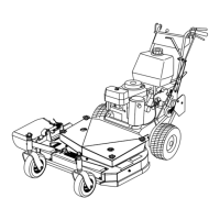
1.Removethehairpincotterpinsandclevispinsfrom
thedriveleversandneutrallocks(Figure35).
Figure35
1.Controlrod
5.Neutrallock
2.Clevispin
6.Hairpincotterpin
3.OperatorPresence
Controllever(OPC)
7.Lefthandleshown
4.Handle8.Drivelever
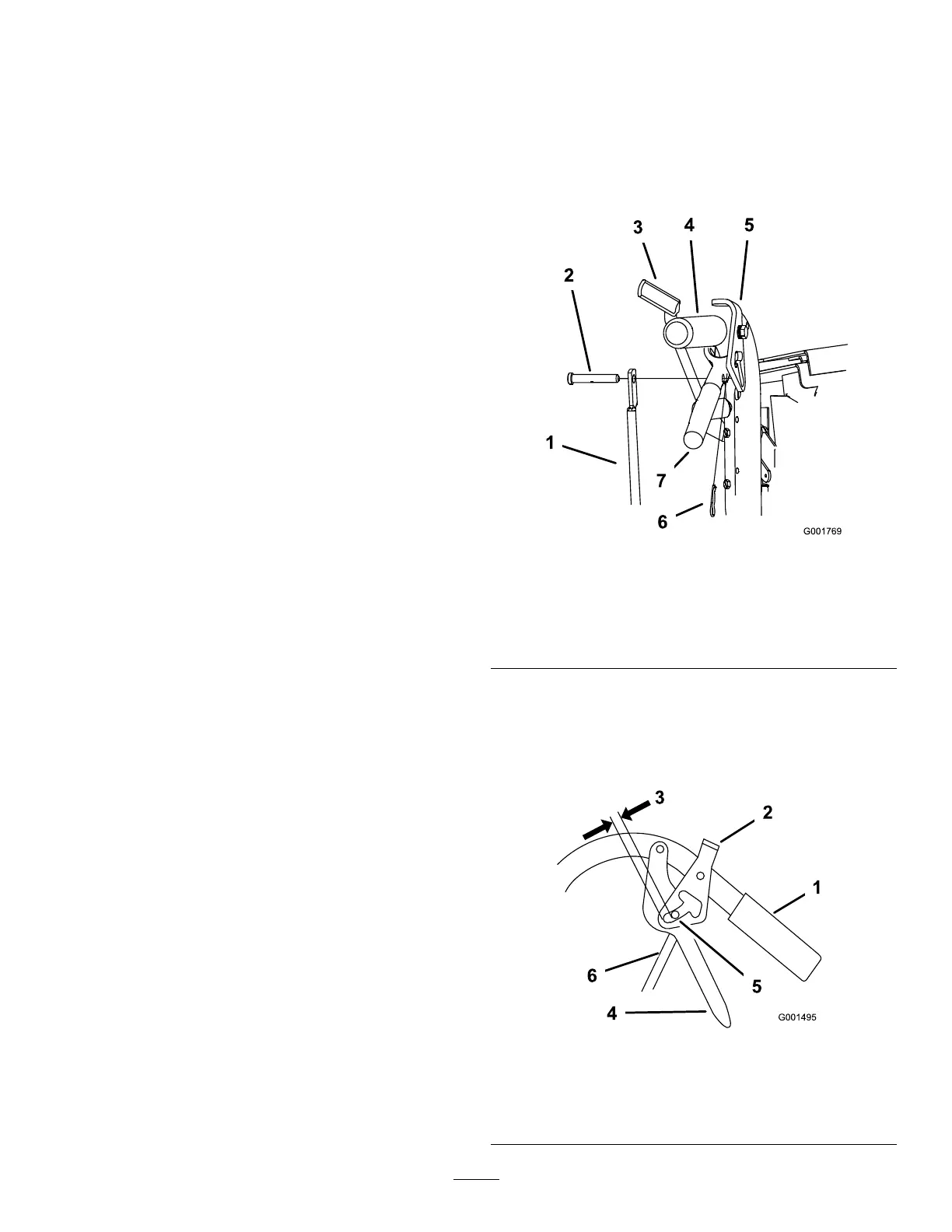
2.Adjustthecontrolrodlengthbythreadingtherodin
oroutoftherodttinguntilthereisa3/16to1/4
inches(5to6mm)clearancebetweenthecontrol
rodandthebottomoftheneutral/parkingbrake
lock(Figure36).
Figure36
1.Handle4.Drivelever
2.Neutral/parkingbrakelock
5.Forwardspeed
3.3/16to1/4inch(5to6
mm)clearance
6.Controlrod
31